MDS 05-6632A01, Rev. F MDS Orbit MCR/ECR Technical Manual 65
NOTE GE MDS is continually certifying the product for different countries and carriers, please contact
GE MDS sales or technical support to inquire about the current certification status for particular
country/carrier.
Orbit MCR supports routing of TCP/UDP/IP data from the Cellular WAN network interface to any of the
other network interfaces (including WiFi or LAN) using the IPsec VPN or network address and port
translation (NAPT) feature and to the COM1 (or COM2) serial port using the terminal server service. The
configuration of these use cases is specified in the respective sections on VPN, Firewall and NAT and
Terminal Service.
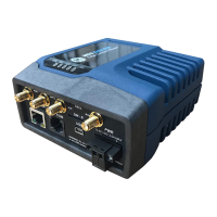
The cellular modem inside the unit supports main (primary) and secondary antenna (for receive diversity).
The primary antenna must be installed for the cell modem to register with the cellular network. It is
strongly recommended that a secondary antenna be installed for achieving a robust cellular link. There
should be no physical obstructions around the antennas. The main and diversity antennas must have at
least 27 dB of isolation from each other to ensure optimal operation of the cellular modem. For Antenna
Installation assistance, see “Antenna Planning and Installation” on Page 31 or contact your local GE MDS
representative. See the below table for approved Antenna Types.
Table 3-4. Approved Cell Antenna Types
Direct Connect, - SMA Paddle
antenna
External Mount, Omni Ant. with
N-Female connector - no cable
Note: requires a metal Ground
Plane
External Mount, Dipole Omni with
N-Female connector - no cable
Table 3-5 describes the Orbit MCR’s LED behavior when using the cellular interface.
Table 3-5. Cell Interface LED Descriptions
No cellular connection
Cell connection
SIM Port(s) - These ports accept a mini SIM card (2FF type) for cell operation. The unit’s cellular
interface will not function without a valid SIM card installed. Users are responsible for obtaining a
provisioned SIM card for the appropriate service plan from their cellular provider. Information on
determining the cell module’s IMSI/IMEI (typically required for provisioning) is provided on Page 75 of
this manual.
CAUTION: Do not insert the SIM card when the unit is powered on.
Card Insertion: The SIM card only inserts one way; do not force it. It should be inserted with the printed
label facing up and the cut-off corner on the left side (see figure below). A small instrument, such as a
flathead screwdriver, may be helpful to gently push the SIM all the way in until it locks.
 Loading...