MDS 05-6632A01, Rev. F MDS Orbit MCR/ECR Technical Manual 33
Antenna Installation Guidance (Licensed Narrowband)
Antennas:
LN transceivers may be used with a number of different antennas. The exact style and gain factor depend
on regulatory constraints and the physical size/layout of your system. Connection is made to the radio via
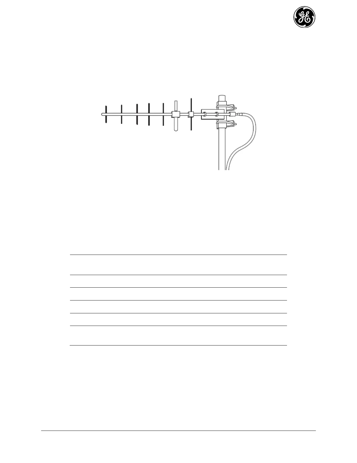
a TNC coaxial connector. A directional Yagi (Figure 2-12) or corner reflector antenna is generally used at
remote sites to minimize interference to and from other users. Antennas of this type are available from
several manufacturers, including GE MDS. Contact your sales representative for details.
Figure 2-12. Typical Yagi Antenna (mounted to mast)
Feedlines:
Selection of an antenna feedline is very important. Poor quality cable should be avoided as it will result in
power losses that may reduce the range and reliability of the radio system. The tables which follow show
the approximate losses that will occur when using various lengths and types of coaxial cable. Regardless
of the type used, the cable should be kept as short as possible to minimize signal loss.
Table 2-7. Signal Loss In Coaxial Cables (at 400 MHz)
 Loading...