x/EN AP/Na7
-54 MiCOM P74
Solution Solution A
1 CT on BC
& 1 CT on
each BS
Solution B
2 CT on BC
& 2 CT on
each BS
Solution C
1 CT on BC
& 2 CT on
each BS
Solution D
2 CT on BC
& 1 CT on
each BS
Solution 1a
Solution 2
Solution 2a
Number of
peripheral units
required
n + 3 n + 6 n + 5 n + 4
If a second bus coupler is added i.e. one bus coupler either side of the bus section
Using solution 1
for the 2
nd
coupler
Using solution 1a
for the 2
nd
coupler
Number of
peripheral units
required
n + 4 n + 8 n + 6 n + 6
TABLE 5: NUMBER OF REQUIRED PU’S FOR FIGURE 35
The number of additional peripheral units being dependant on the number of bus section/bus
coupler CTs. The type of peripheral unit used for each bay will depend on the i/o
requirements of the bay in question.
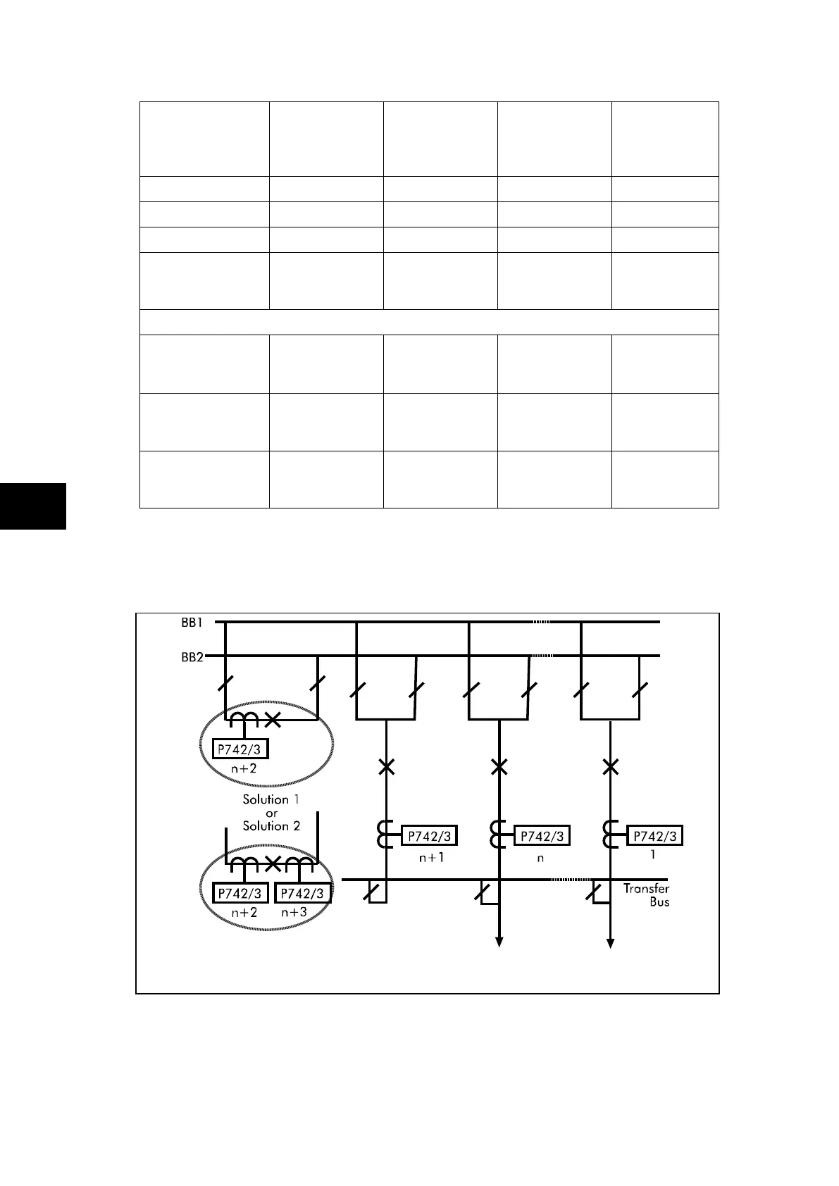
FIGURE 36: DOUBLE BUSBAR APPLICATION WITH A BUS COUPLER.
THE TRANSFER BUSBAR IS NOT INCLUDED
IN THE PROTECTION ZONE.
The above example shows a double busbar with a bus coupler and a transfer busbar. As
the transfer busbar is on the line side of all the feeder CTs, it is not included in the protected
zone it can be considered similarly to figure 37, an additional peripheral unit must be
included for the transfer bay.