pplication Notes
P74x/EN AP/N
1, P742, P743 (AP) 6-
It is split into two zones. There are n feeders connected to the busbar. The bus coupler
circuit breaker can have either a single CT (solution 1) on one side or CTs on both sides
(solution 2). This configuration requires 1 central unit and n + 2 peripheral units for solution
1 or n + 3 peripheral units for solution 2. (The additional peripheral units being for the bus
coupler CTs and the transfer bay). The type of peripheral unit used for each bay will depend
on the i/o requirements of the bay in question.
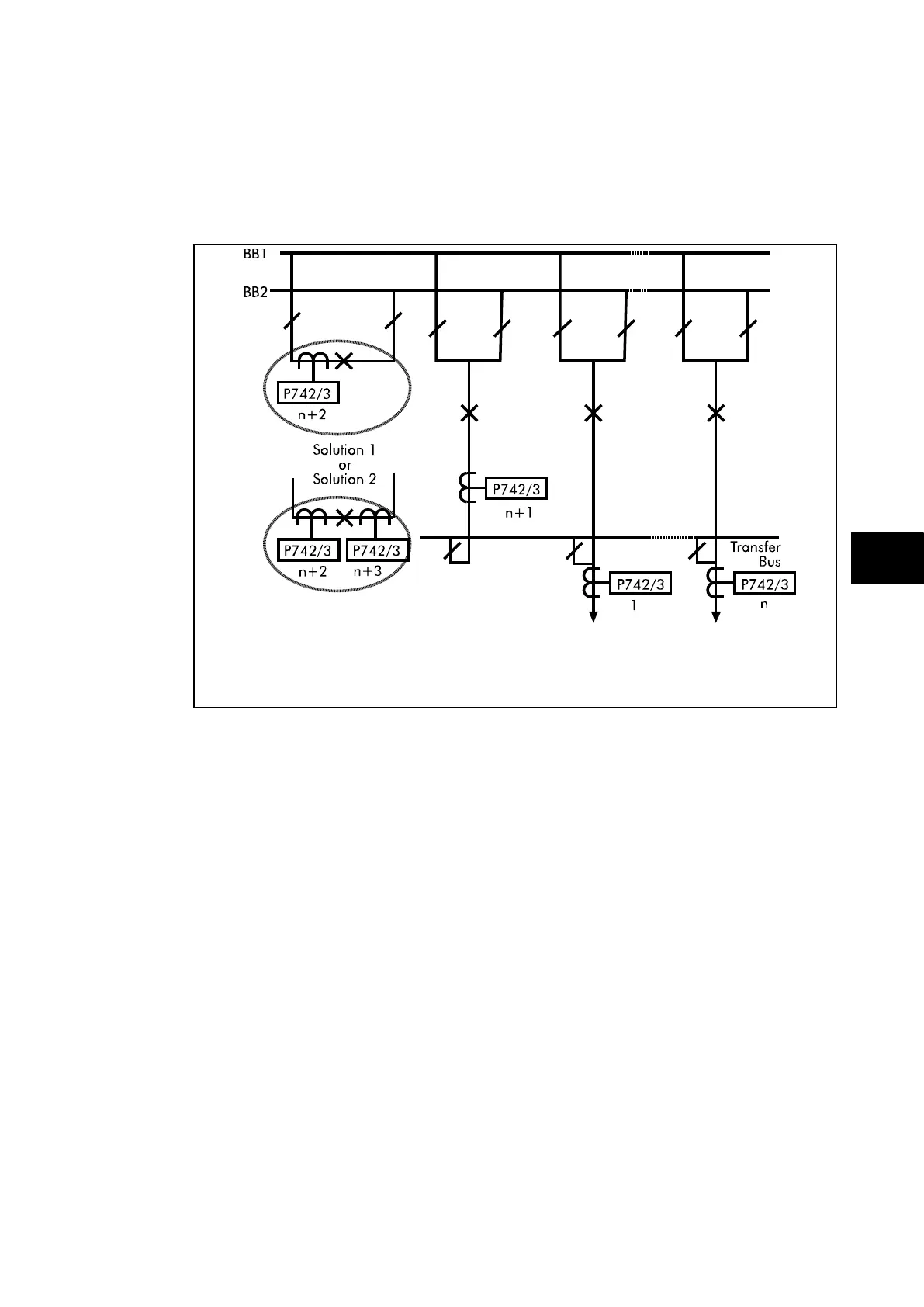
FIGURE 37: DOUBLE BUSBAR APPLICATION WITH A BUS COUPLER.
THE TRANSFER BUSBAR IS INCLUDED IN THE PROTECTION ZONE.
The above example shows a double busbar with a bus coupler and a transfer busbar. The
transfer busbar is on the bus side of all the feeder CTs, it is included in the protected zone. It
can be considered similarly to figure 38, where an additional peripheral unit has been
included for the transfer bay. The only difference being the positioning of the CTs and
therefore the protection.
Again it is split into two zones. With an additional zone for the transfer bay, there are n
feeders connected to the busbar. The bus coupler circuit breaker can have either a single
CT (solution 1) on one side or CTs on both sides (solution 2). This configuration requires 1
central unit and n + 2 peripheral units for solution 1 or n + 3 peripheral units for solution 2.
(The additional peripheral units being for the bus coupler CTs and the transfer bay). The
type of peripheral unit used for each bay will depend on the i/o requirements of the bay in
question.