x/EN PL/Na7
7-
MiCOM P74
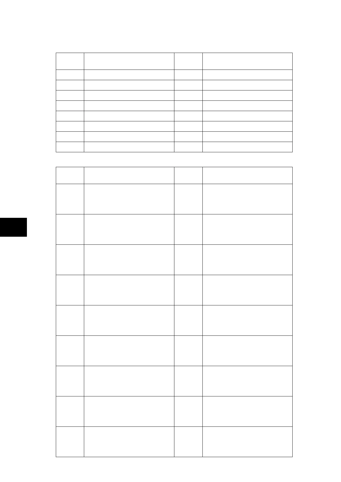
Peripheral Unit P742:
LED
Number
LED Input Connection/Text Latched P74x LED Function Indication
1 LED 1 Red No Isolator 1 Closed
2 LED 2 Red No Isolator 2 Closed
3 LED 3 Red No Isolator 3 Closed
4 LED 4 Red Yes Trip on CU 50BF backtrip order
5 LED 5 Red Yes Trip on CU 87BB trip order
6 LED 6 Red Yes Dead Zone fault
7 LED 7 Red No Circuit Breaker out of service
8 LED 8 Red No Fiber communication Error
Peripheral Unit P743:
LED
Number
LED Input Connection/Text Latched P74x LED Function Indication
1
LED1 Red
LED1 Yellow
LED1 Green
No
Isolator 1 Closed
Isolator 1 Status Alarm
Isolator 1 Open
2
LED2 Red
LED2 Yellow
LED2 Green
No
Isolator 2 Closed
Isolator 2 Status Alarm
Isolator 2 Open
3
LED3 Red
LED3 Yellow
LED3 Green
No
Isolator 3 Closed
Isolator 3 Status Alarm
Isolator 3 Open
4
LED4 Red
LED4 Yellow
LED4 Green
Yes
Trip on CU 50BF backtrip order
Not used
Not used
5
LED5 Red
LED5 Yellow
LED5 Green
Yes
Trip on CU 87BB trip order
Not used
Not used
6
LED6 Red
LED6 Yellow
LED6 Green
Yes
Dead Zone fault
Not used
Not used
7
LED7 Red
LED7 Yellow
LED7 Green
No
Circuit Breaker out of service
Not used
Circuit Breaker healthy
8
LED8 Red
LED8 Yellow
LED8 Green
No
Fiber communication Error
Fiber communication to change
Fiber communication healthy
9
FnKey LED1 Red
FnKey LED1 Yellow
FnKey LED1 Green
No
Not used
Not used
Reset PU Indications