1-18
Network diagram
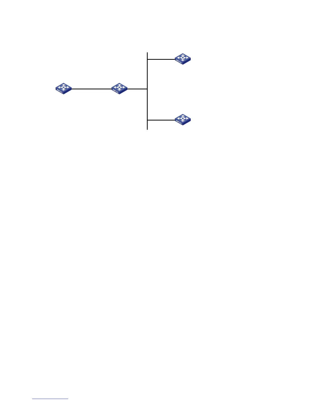
Figure 1-8 Network diagram for the NTP broadcast mode configuration
Vlan-int2
1.0.1.31/24
Vlan-int2
3.0.1.31/24
Vlan-int2
3.0.1.32/24
Device A Device B
Device C
Device D
Configuration procedure
1) Configure Device C.
# Enter system view.
<DeviceC> system-view
# Set Device C as the broadcast server, which sends broadcast messages through Vlan-interface2.
[DeviceC] interface Vlan-interface 2
[DeviceC-Vlan-interface2] ntp-service broadcast-server
2) Configure Device A. (perform the same configuration on Device D)
# Enter system view.
<DeviceA> system-view
# Set Device A as a broadcast client.
[DeviceA] interface Vlan-interface 2
[DeviceA-Vlan-interface2] ntp-service broadcast-client
After the above configurations, Device A and Device D will listen to broadcast messages through their
own Vlan-interface2, and Device C will send broadcast messages through Vlan-interface2. Because
Device A and Device C do not share the same network segment, Device A cannot receive broadcast
messages from Device C, while Device D is synchronized to Device C after receiving broadcast
messages from Device C.
View the NTP status of Device D after the clock synchronization.
[DeviceD] display ntp-service status
Clock status: synchronized
Clock stratum: 3
Reference clock ID: 3.0.1.31
Nominal frequency: 100.0000 Hz
Actual frequency: 100.0000 Hz
Clock precision: 2^18
Clock offset: 198.7425 ms
Root delay: 27.47 ms
Root dispersion: 208.39 ms
Peer dispersion: 9.63 ms
Reference time: 17:03:32.022 UTC Apr 2 2007 (BF422AE4.05AEA86C)

 Loading...


