1-19
The output information indicates that Device D is synchronized to Device C, with the clock stratum level
of 3, one level lower than that of Device C.
# View the information about the NTP sessions of Device D and you can see that a connection is
established between Device D and Device C.
[DeviceD] display ntp-service sessions
source reference stra reach poll now offset delay disper
**************************************************************************
[1234]3.0.1.31 127.127.1.0 2 1 64 377 26.1 199.53 9.7
note: 1 source(master),2 source(peer),3 selected,4 candidate,5 configured Total
associations : 1
Configuring NTP Multicast Mode
Network requirements
z The local clock of Device C is set as the NTP master clock, with a clock stratum level of 2.
Configure Device C to work in the NTP multicast server mode and advertise multicast NTP
messages through Vlan-interface2.
z Device A and Device D are two S3100 Ethernet switches. Configure Device A and Device D to
work in the NTP multicast client mode and listen to multicast messages through their own
Vlan-interface2.
Network diagram
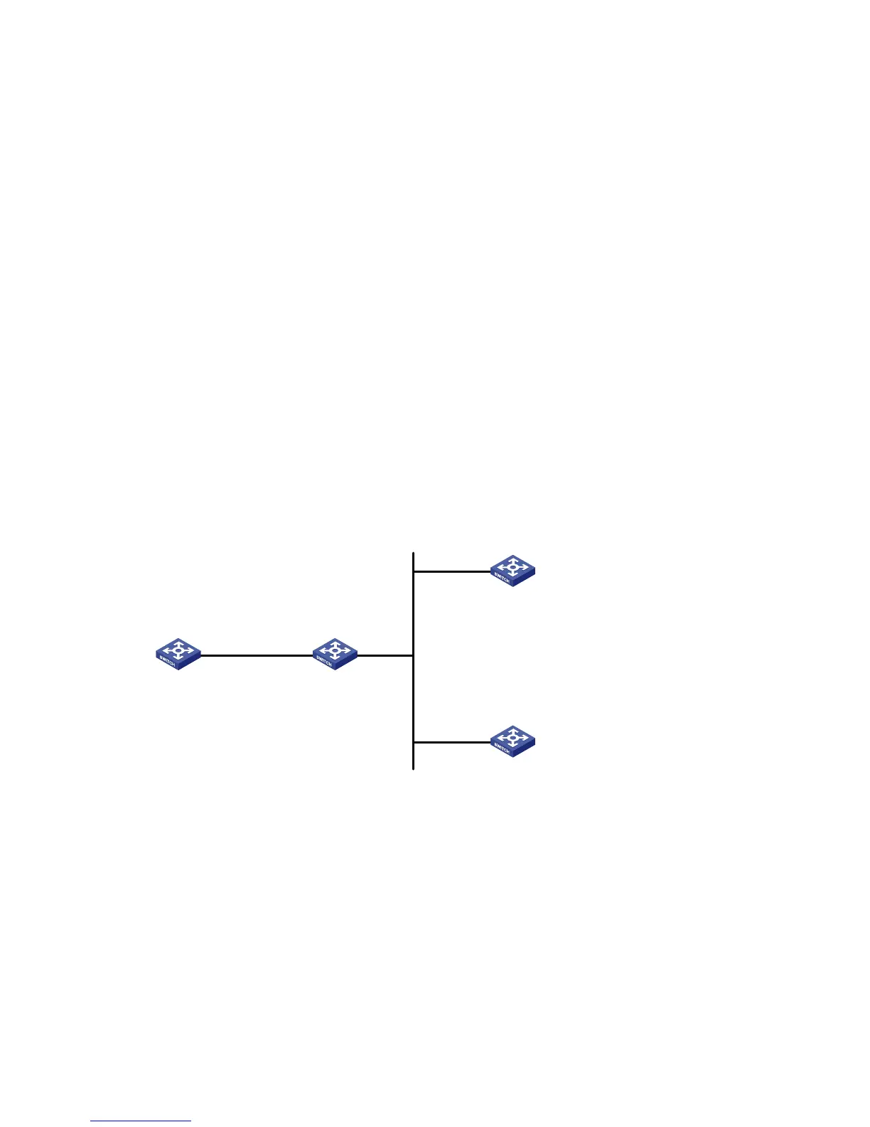
Figure 1-9 Network diagram for NTP multicast mode configuration
Vlan-int2
1.0.1.31/24
Vlan-int2
3.0.1.31/24
Vlan-int2
3.0.1.32/24
Device A Device B
Device C
Device D
Configuration procedure
1) Configure Device C.
# Enter system view.
<DeviceC> system-view
# Set Device C as a multicast server to send multicast messages through Vlan-interface2.
[DeviceC] interface Vlan-interface 2
[DeviceC-Vlan-interface2] ntp-service multicast-server
2) Configure Device A (perform the same configuration on Device D).
# Enter system view.
<DeviceA> system-view
# Set Device A as a multicast client to listen to multicast messages through Vlan-interface2.

 Loading...


