8.1 Outline of External I/O
103
8
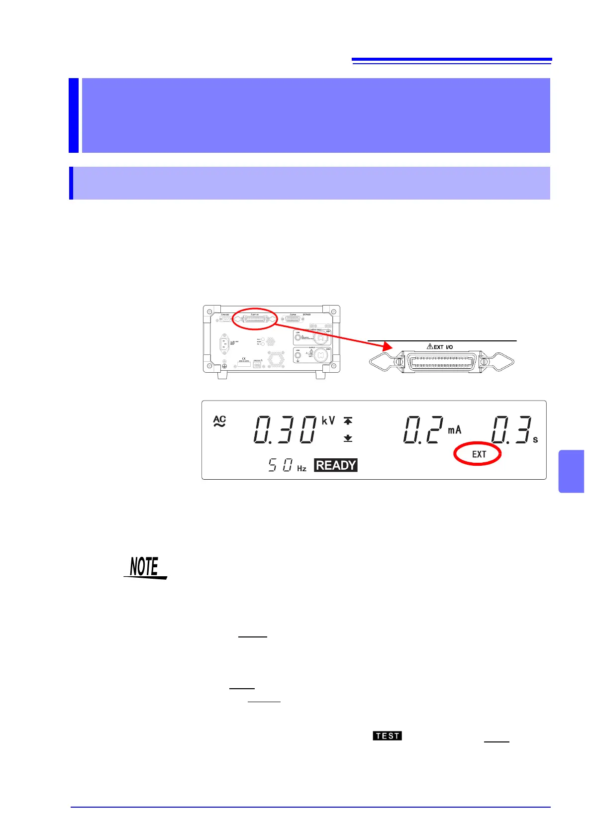
External I/O is found on the back of the instrument and indicates the different
modes of the instrument, such as READY, TEST, etc. and PASS, FAIL results of
tests with signals. It can also control the instrument when signals for starting the
test, START, stopping the test, STOP or selecting a file, File Selection are input-
ted. It enables safe measurement by using interlock terminals.
See "8.3 Inter-lock Function" (p. 111)
All signal lines are insulated internally with a photocoupler. A power voltage of 15
V (0.1 A), insulated from the internal supply, is output from the external I/O termi-
nal. This voltage can be used as external power. If the unit power capacity is
insufficient, add an external power supply.
External Interface Chapter 8
8.1 Outline of External I/O
There is a priority hierarchy for the START keys.
Priority hierarchy: Remote Control Box > EXT I/O > Front panel of the 3174
(3174-01)
Note that when a START key with a higher priority is in use, lower-priority keys
are disabled.
<Ex.>
• When EXT-E
of the external I/O terminal is at LOW level (EXT lights up), the
unit START key is disabled.
• If you use the Remote Control Box, the START signal for the external I/O ter-
minal is disabled.
• The TEST
signal is turned ON when TEST on the fluorescent indicator lights
up. The H.V.ON
signal is turned on when the DANGER lamp lights up. The
two signals are turned OFF at the same time.
• Upon startup of the test, although flashes until the output voltage
reaches the set test voltage or during the ramp-up time, the TEST
signal is
ON.