47
4
This chapter describes how to set insulation-resistance test condi-
tions and the proper testing procedure.Read "Chapter 2 Testing
Arrangements" (p. 17), and make the necessary preparations for
testing.
Refer to "Chapter 5 Automatic Test" (p. 69) for carrying out withstanding and
insulation-resistance tests consecutively.
Insulation-
Resistance Test Chapter 4
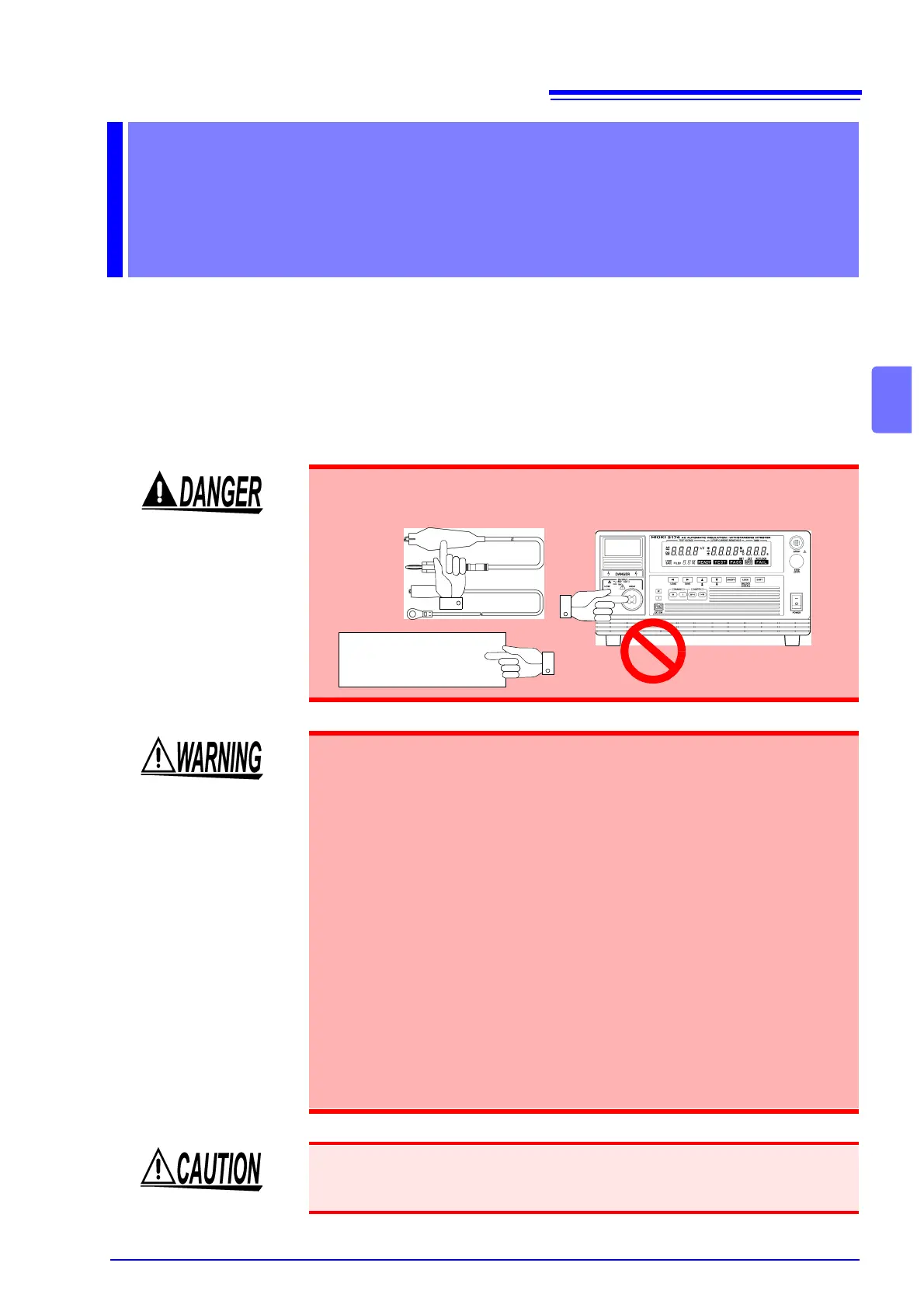
To prevent electric shock, when the DANGER lamp is lit or during the test,
never touch the voltage output terminals, test lead, or the tested object.
Tested object
• To prevent electric shocks, do not connect to or remove the test lead
from the tested object when there is a voltage supply during the test.
There is a danger of a voltage higher than the pre-set voltage being sup-
plied due to the stabilization function of the voltage output. When this
happens, the instrument may malfunction due to the noise produced.
• The instrument and peripheral electrical devices may not function prop-
erly when the tested object’s insulation is broken or when the test leads
are not connected properly. When this happens, connect a ferrite core or
a resistor to the test lead on the high voltage side. Be careful of a dip in
the test voltage caused by the rated power, withstanding voltage and
resistor when choosing a resistor.
• Wear insulated gloves and confirm that automatic control is off before
changing the tested object or touching the test lead and tested object
directly.
• To increase test efficiency, this instrument can be controlled by EXT I/O
or RS-232C and GP-IB and can start tests automatically. As a result, there
is a danger of electric shock accidents. Measures to prevent people from
coming near the instrument or the tested object unintentionally must be
taken when starting the instrument automatically.
• When the tested object in use possesses an inductivity like a coil, a voltage
higher than the pre-set voltage may appear transitionally, causing damage in
the tested object.