29
3
This chapter describes how to set withstand-voltage test conditions
and the proper testing procedure. Read "Chapter 2 Testing
Arrangements" (p. 17), and make the necessary preparations for
testing.
Refer to "Chapter 5 Automatic Test" (p. 69) for carrying out withstanding and
insulation-resistance tests consecutively.
Withstand-
Voltage Test Chapter 3
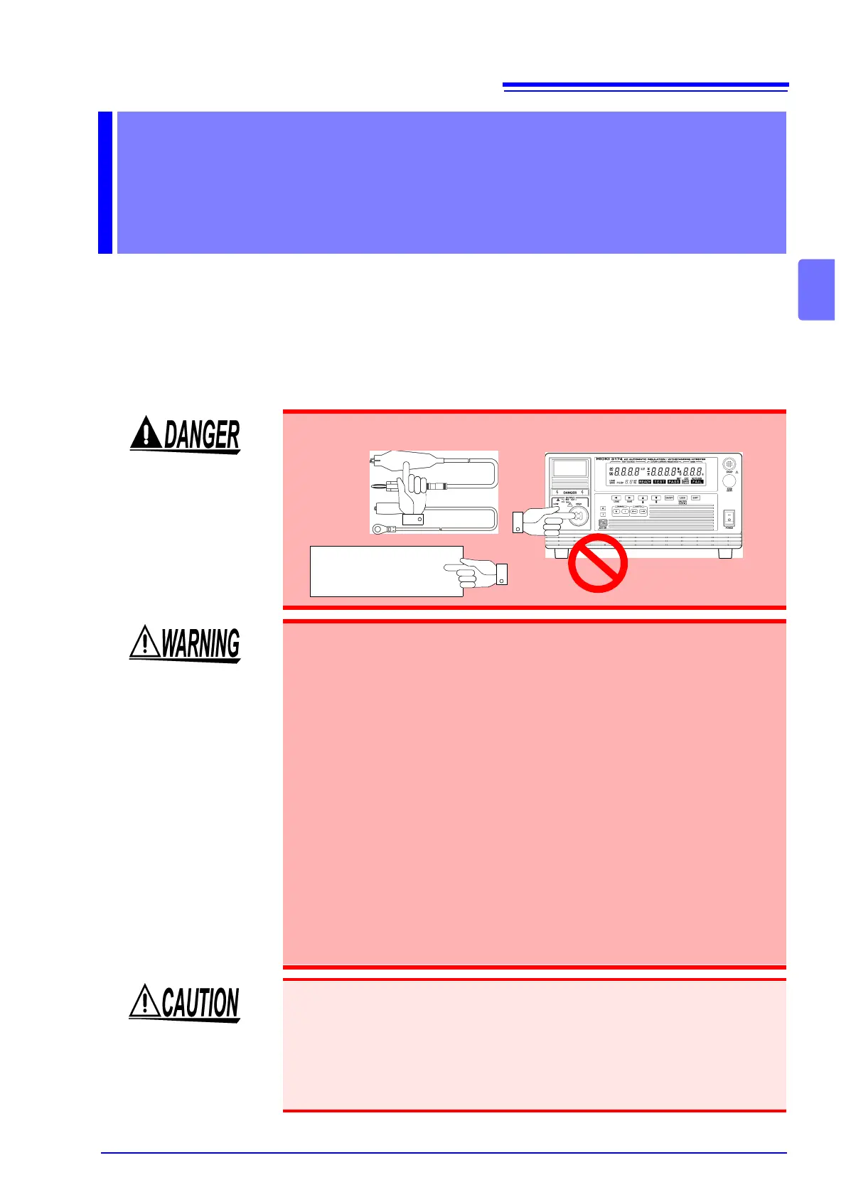
To prevent electric shock, when the DANGER lamp is lit or during the test,
never touch the voltage output terminals, test lead, or the tested object.
• To prevent electric shocks, do not connect to or remove the test lead
from the tested object when there is a voltage supply during the test.
There is a danger of a voltage higher than the pre-set voltage being sup-
plied due to the stabilization function of the voltage output. When this
happens, the instrument may malfunction due to the noise produced.
• The instrument and peripheral electrical devices may not function prop-
erly when the tested object’s insulation is broken or when the test leads
are not connected properly. When this happens, connect a ferrite core or
a resistor to the test lead on the high voltage side. Be careful of a dip in
the test voltage caused by the rated power, withstanding voltage and
resistor when choosing a resistor.
• Wear insulated gloves and confirm that automatic control is off before
changing the tested object or touching the test lead and tested object
directly.
• To increase test efficiency, this instrument can be controlled by EXT I/O
or RS-232C and GP-IB and can start tests automatically. As a result, there
is a danger of electric shock accidents. Measures to prevent people from
coming near the instrument or the tested object unintentionally must be
taken when starting the instrument automatically.
• When the tested object in use shows dependency on voltage (impedance of
ceramic condenser, etc.), the waveforms of the output voltage may become
distorted. The tested object may malfunction depending on the distortion of the
waveforms.
• When the tested object in use possesses an inductivity like a coil, a voltage
higher than the pre-set voltage may appear transitionally, causing damage in
the tested object.
Tested object