8.2 Example of Signal Connection
107
8
• The instrument can be controlled externally using the external I/O input signal.
Saved test condition can also be selected. Provide a connector that conforms
to the external I/O specifications.
• To enable the external I/O signal, set the EXT-E
signal (Pin 7) to LOW level.
Connect the EXT-E
signal to ISO.COM for the GND signal (Pins 15 to 18),
which is insulated from the instrument's internal power supply.
• To enable the memory selection terminal, set the MEM
-E signal (pin 27) to
LOW level. When downloading the saved test data, connect the MEM
-E signal
to ISO.COM for the GND signal (Pins 15 to 18), which is insulated from the
instrument's internal power supply.
See"Connector pin numbering" (p. 104)
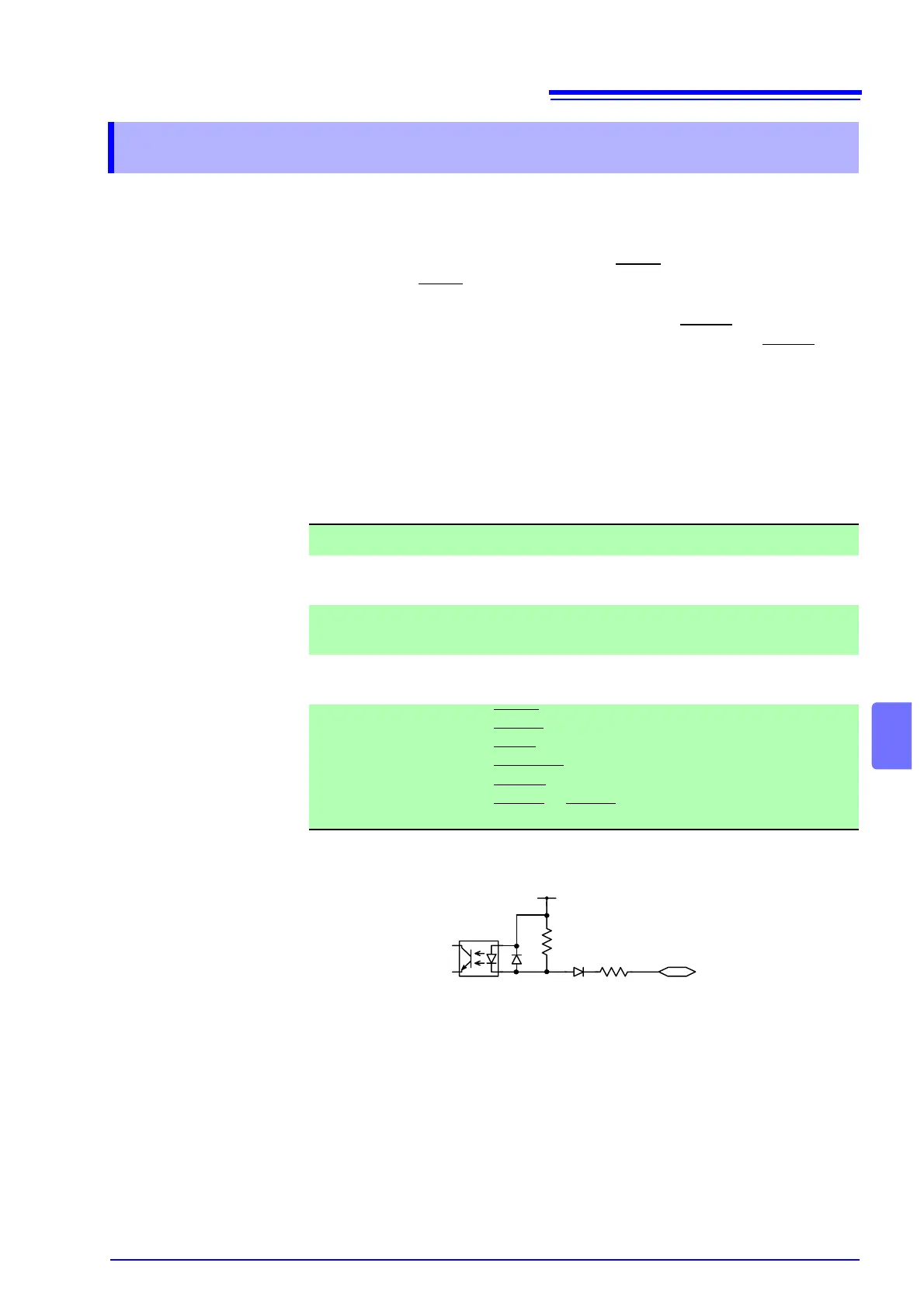
Example of Input Signal Connection
8.2 Example of Signal Connection
EXT I/O Input signals Specifications
Input signal Active low input (photocoupler isolated)
Maximum input
voltage
30 V DC
HIGH level voltage
(HI)
More than 15 V DC or open
LOW level voltage
(LO)
5 V DC or less
Signal name EXT-E : External I/O valid
START
: Test starts
STOP
: Test stops
INT.LOCK
: Inter-lock
MEM-E
: Memory selection terminal valid
MEM-0 to MEM-3 : Memory selection terminal
10 kΩ
2.2 kΩ
ISO.DCV (15 V)
External I/O
input terminal
Photocoupler