9.2 Connection and Setting Procedures
123
99
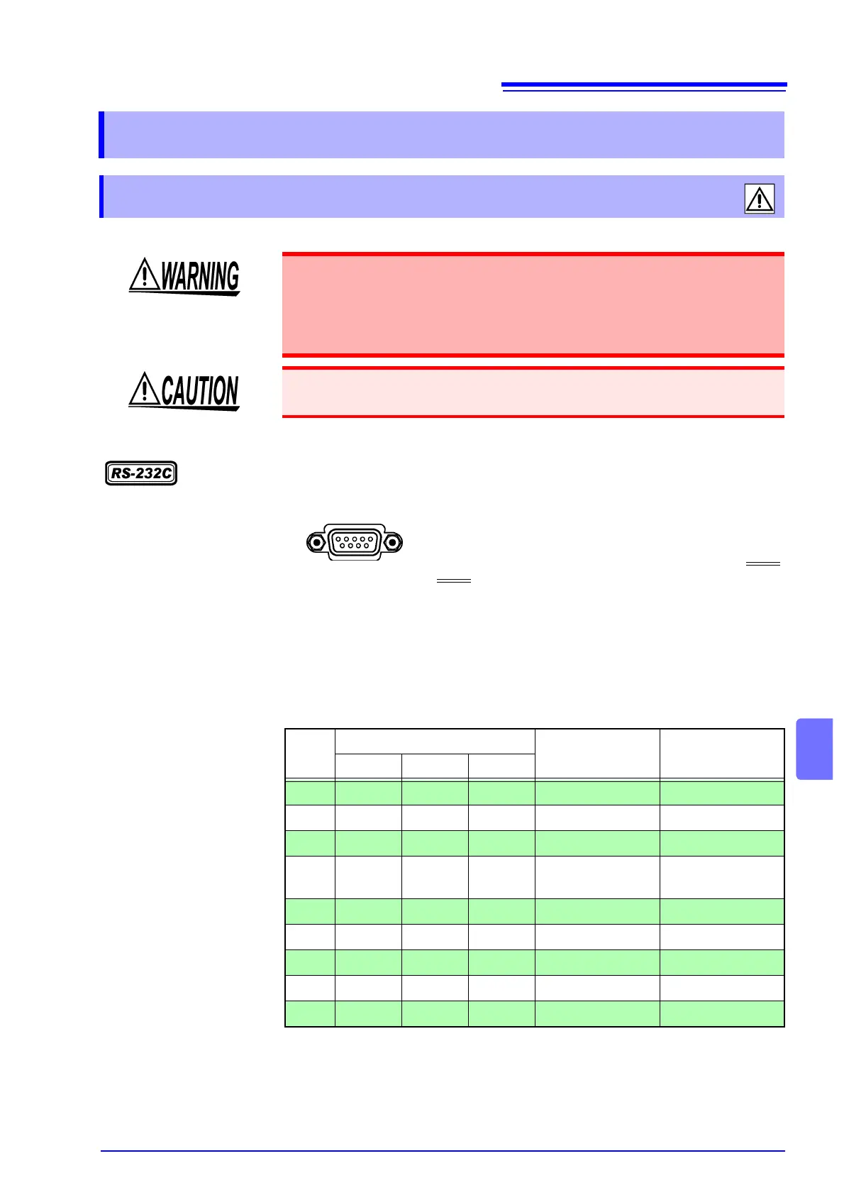
RS-232C connector
9.2 Connection and Setting Procedures
9.2.1 Connecting the Connector
• Always turn both devices OFF when connecting and disconnecting an
interface connector. Otherwise, an electric shock accident may occur.
• After connecting, always tighten the connector screws.The mounting
screws must be firmly tightened or the instrument may not perform to
specifications, or may even fail.
To avoid damage to the instrument, do not short-circuit the terminal and do not
input voltage to the terminal.
Male 9-pin D-sub
#4-40 attaching screws
Connect the RS-232C cable.
When connecting the controller (DTE), prepare a cros
cable that meets the specifications of the connector o
the unit and the connector of the controller.
The I/O connector is a DTE (Data Terminal Equipment) configuration.
This instrument uses pins 2, 3 and 5. Connect pins 7 and 8. The other pins
are unconnected.
6 7 8 9
1 2 3 4 5
Pin No.
Signal name
Signal Note
Common EIA JIS
1 DCD CF CD Unused Not connected
2 RxD BB RD Receive Data
3 TxD BA SD Transmitted Data
4 DTR CD ER Data Terminal
Ready
Not connected
5 GND AB SG Signal Ground
6 DSR CC DR Unused Not connected
7 RTS CA RS Request to Send Connect to 8
8 CTS CB CS Unused Connect to 7
9 RI CE CI Unused Not connected