8.2 Example of Signal Connection
109
8
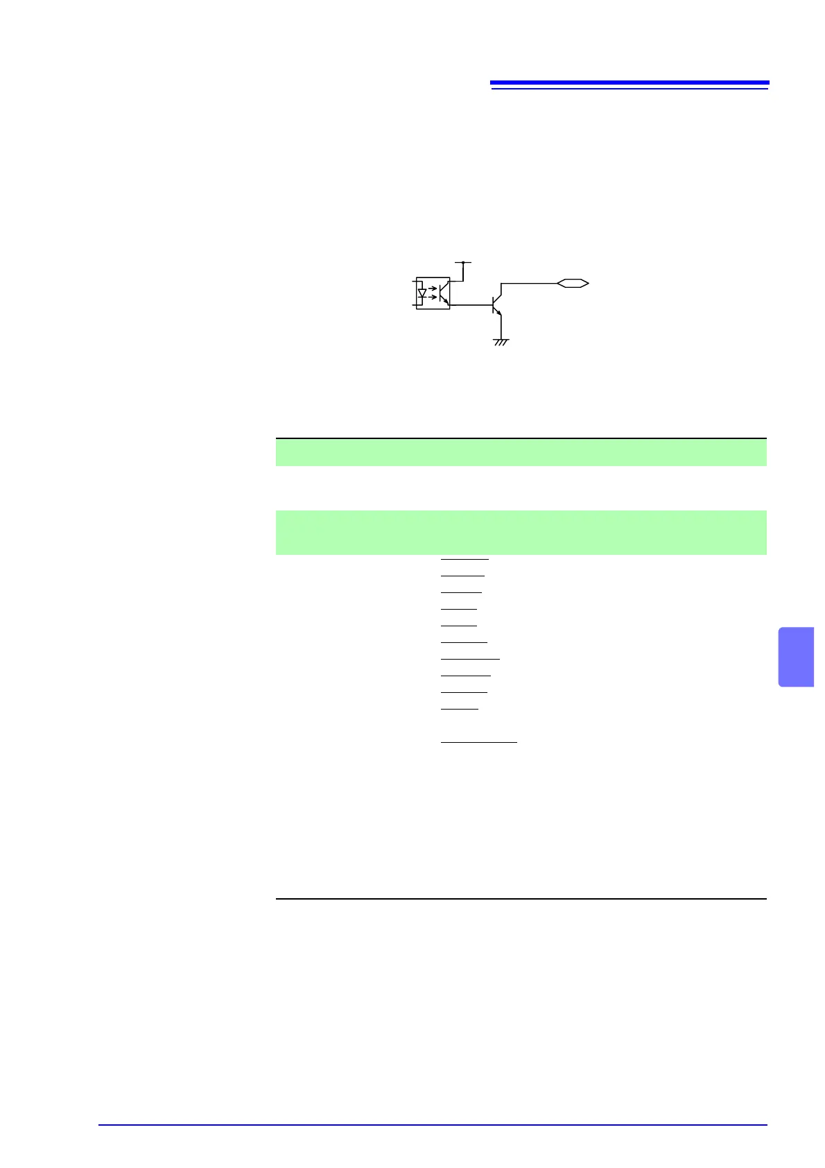
Example of Output Signal Connection
The output signal becomes LOW level depending on the condition of the instru-
ment. Prepare a connector that conforms to the External I/O Specifications.
For details, refer to output examples in "8.6 Timing Chart" (p. 115)
* 1 (H) : transistor OFF
0 (L) : transistor ON
EXT I/O Output signals Specifications
Output signal Open collector output
Maximum output
current
DC100 mA/1
Output Saturation
Voltage
1.5 V DC or less
Signal name READY : READY mode
U-FAIL
: UPPER FAIL status
L-FAIL
: LOWER FAIL status
PASS
: PASS status
TEST
: Testing
H.V.ON
: Supplying voltage
W-MODE
: Screen of withstand-voltage test
I-MODE
: Screen of insulation-resistance test
W-FAIL
: FAIL result for withstand test
I-FAIL
: FAIL result for insulation-resistance
test
MODE0
to 1: Status indicating signals
1 (H) 1 (H) W mode
1 (H) 0 (L) I mode
0 (L) 1 (H) W-I mode
0 (L) 0 (L) I-W mode
ISO.DCV (15 V)
External I/O
output terminal
ISO.COM
MODE1
MODE0