8.3 Inter-lock Function
112
Procedure for
Using
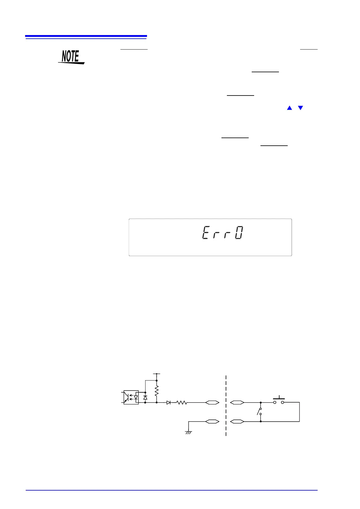
• The inter-lock function is active when the INT.LOCK terminal is open, with the
following displayed: To disable the function, connect the INT.LOCK
terminal to
ISO.COM and set it to LOW level. The instrument changes to READY status
once the inter-lock function is disabled.
• When selecting the “1:ON” at the “Inter-lock” for the optional function, the test
will not be carried out unless the Pin 10 of the external I/O terminal is set to
Low. In this case, “Err0” will be shown.
Example of
Connections
For example, to ensure the safety of workers, the instrument and the tested
object are placed in a box so that they are not in contact with each other. The
door of the box cover is also equipped with a switch that works in combination
with the inter-lock function. If a connection is made to the switch, the inter-lock
function is enabled when the box cover is opened. When the cover is closed, the
function is disabled, making the instrument ready for testing.
All keys are inactive provided that the inter-lock function is active. As a result,
once the instrument is mounted in the box, the settings cannot be changed. In
such a case, connect the setting adjustment switch the door switch such that
these switches are arranged in parallel, as shown below:
• The INT.LOCK terminal is always active, regardless of the status of the EXT-E
terminal.
• If "0: OFF" is selected for "Inter-lock" in Optional Functions, the inter-lock
function is inactive, regardless of the status of the INT.LOCK
terminal. The
function is set at "0: OFF" by default. If the inter-lock function is to be used, be
sure to select "1: ON"
• Interlock function can only be set when the INT.LOCK
(Pin 10) at the external
I/O terminal is set to LOW. When the Pin is at HIGH, pressing the / keys
will not change the “0: OFF” setting.
10 kΩ
2.2 kΩ
ISO.DCV (15 V)
Inter-lock
input terminal
ISO.COM
Door switch
Inside the 3174
Photocoupler
Setting adjustmen
switch