1.3 Names and Functions of Parts
11
1
The diagram shows a 3174-01 (with GP-IB) AC Automatic Insulation/Withstand-
ing HiTester.
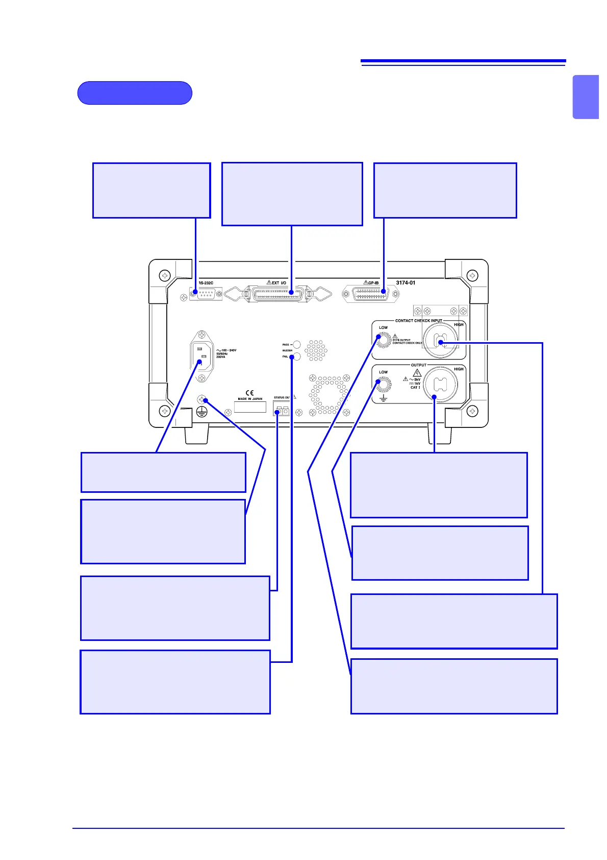
Rear Panel
GP-IB connector (3174-01)
Used for remote control with
GP-IB.
EXT I/O connector
For output of 3174 state
and input of start and stop
signals.
RS-232C connector
Used for remote con-
trol with RS-232C.
Power Inlet
Connect the supplied power cord
here
LOW contact check terminal
A low-voltage terminal for contact check.
Protective conductor terminal
Used to earth a protective
ground wire. Be sure to make
grounding connections before
starting a test.
Status Out Relay Terminal
When conditions pre-set in the Status
Out setting are met, the relay connec-
tion gets switched ON.
Buzzer adjustment knob
Used for buzzer sound adjustment.
Two knobs are provided: one for PASS
screening and one for FAIL screening.
LOW voltage output terminal
A low-voltage terminal for voltage
output. Contains the same electrical
potential as this units casing.
HIGH voltage output terminal
A high-voltage terminal for volt-
age output. Connected to the
HIGH terminal on the front panel.
HIGH contact check terminal
A high-voltage terminal for contact check.
Use the Slip Prevention Plate.