2.4 Connecting the Test Lead
22
Contact check function
By measuring the terminal voltage of the tested object, it is possible to confirm
whether a test voltage is supplied to the tested object or not (Contact check func-
tion).
To use the Contact check function, besides the test output terminal, a set of
9615 H.V. Test Lead for test is necessary. (optional)
For this instrument, the voltage detected by the Contact check terminal will be
differentiated from the test voltage and referred to as the contact voltage.
When the Contact voltage is smaller than the pre-set lower-limit voltage for con-
tact check, broken wire or poor connection is suspected and a contact error will
be displayed (Refer to "3.1.7", "4.1.5 Setting the Confirmation Voltage used for
upper and lower-limits for Contact Check", "11.3 Error Indication" for errors). By
setting an upper-limit voltage for Contact check, detection for any abnormality
(supply of voltage higher than the pre-set value) in the output voltage is possible.
When the Contact check terminal is connected to the tested object, ensure that
the test lead for the Contact check does not directly touch the test lead for the
test as shown in the diagram (ensure that the test lead for the Contact check
touches the test lead for the test through the terminal for the tested object).
If the test lead for the Contact check directly touches the test lead for the test, a
broken wire will be detected but a supply of test voltage to the tested object can-
not be confirmed.
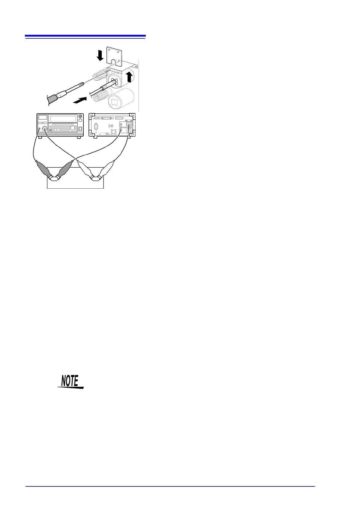
Remove the slip protection plate of the term
nals for Contact Check and connect the te
leads in the same way as steps 2 to 4.
9. Connect the test lead of the LOW Conta
Check terminal to the tested object.
Make sure the probe on the LOW Conta
Check terminal side does not directly touc
the probe on the LOW Voltage Output Term
nal side during this process.
Ensure the connection is secure so that it w
not come off during the test.
10. Connect the probe on the HIGH Conta
Check terminal side to the tested object a
well.
11. Put back the slip protection plate after con
nection.
8
11
9
10
Tested object
• When the contact check terminal on the LOW side is connected not to the
tested object but to GND, an accurate contact check cannot be carried out.
Ensure that the contact check terminal on the LOW side does not touch the
GND even when it is removed.
• A voltage of approximately DC15 V runs through the contact check terminals.
During insulation-resistance measurements, when the LOW Contact Check
terminal is connected to the HIGH measurement terminal, a voltage of approx-
imately 15 V will be indicated however this is not a malfunction.