Section 4 - Alignment & Calibration
4-21
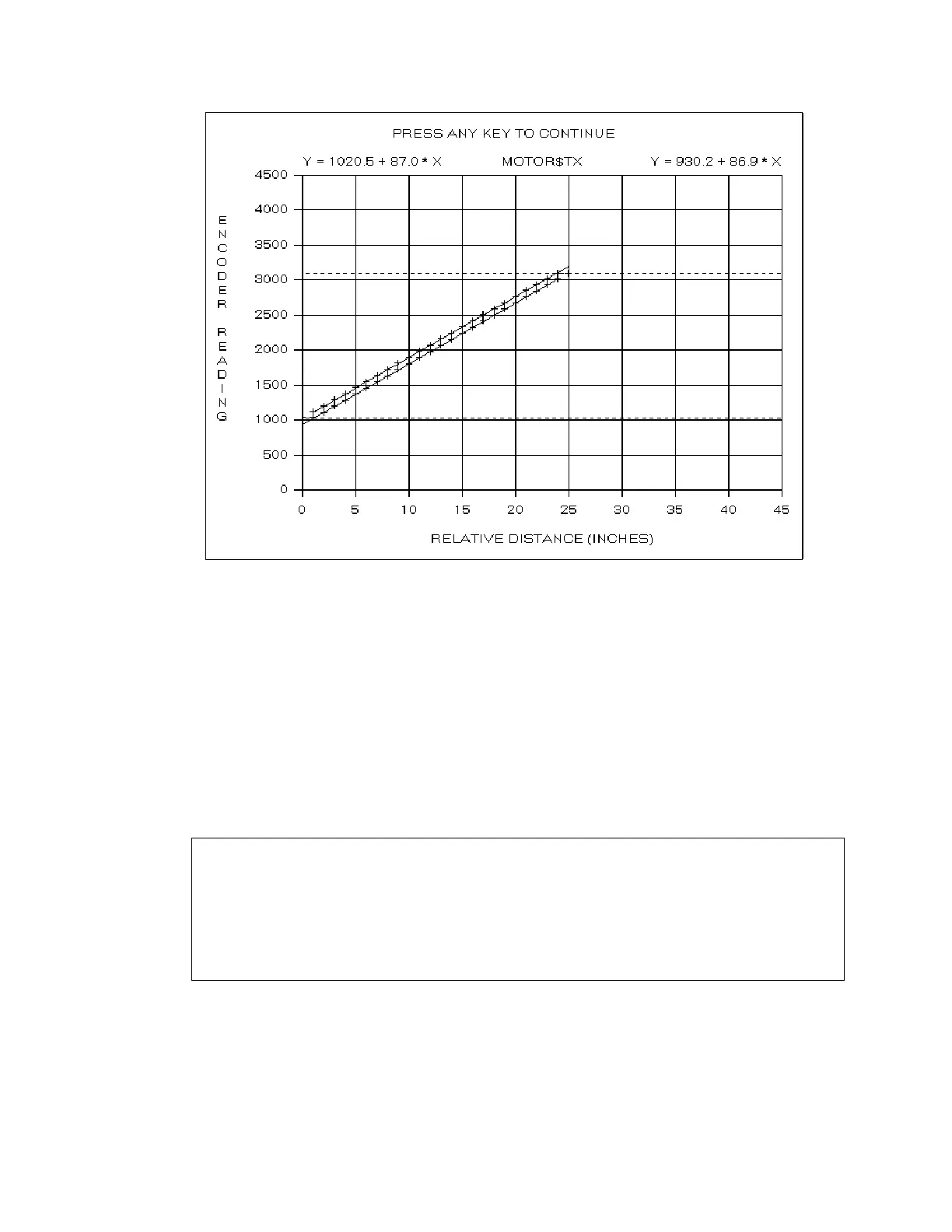
When the calibration scan completes, the program computes the linear fits to the positive and
negative motion. The linear fit parameters are displayed at the top left and top right of the
plot in the form Y = Intercept + Slope * X. The two slopes (87.0 and 86.9 in the example
below) should be within 0.3 of each other.
The program displays the positive and negative limits as horizontal dashed lines (
Note:
The
PosLimitOffset
and
NegLimitOffset
entries in the
[TxMotor]
section of the
hardware.ini
file determine the motion limits relative to the mechanical stops. If these
entries are not present, or are zero, the motion limits are set to the mechanical limits.
The program then changes the plot title to
PRESS ANY KEY TO CONTINUE
. Press the
<Enter>
key and the program prompts
motor_direction=1
calibrate_position=1,2287,27446,43,12563,1026,1026,3096
pos_limit_position=604777
neg_limit_position=0
Update Driver INI-File [Y/N] ?
The
motor_direction
,
calibrate_position
,
pos_limit_position
and
neg_limit_position
fields have the same interpretation as discussed under MOTOR$AY.