QDR
4500 Technical Manual
6-18
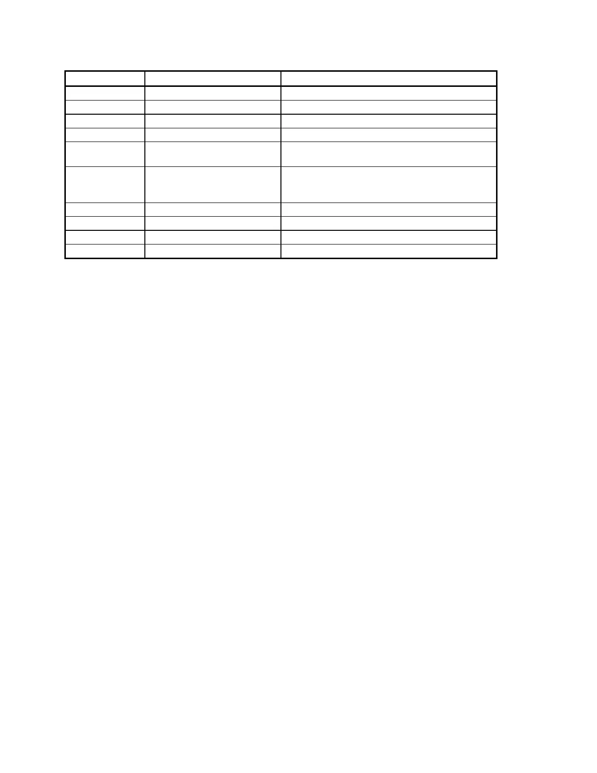
Jumper Label Possible problem Refer to...
Tape switches SECTION 7
Panel Control Panel Table 2-9, Figure 5-2, SECTION 8
Controller Panel Controller
C-Arm Interface Board Table 2-10, Figure 2-7, Figure 2-8, Figure 5-8
C-Arm Components connected to
the C-Arm Interface Board
SECTION 8
Motor Controller PCBs Figure 2-2, Figure 2-3, Figure 2-4, Figure 5-1,
Figure 5-2, Figure 5-4, Figure 5-5, Figure 5-6,
SECTION 8
Distribution Cabling SECTION 2
X-Ray Controller Figure 2-7, Figure 2-8, Figure 2-9, SECTION 8
All jumpers out No instrument power
Check Power Line Voltage
heading, Page 3-18
Emergency stop switch on See Figure 5-2 (Control Panel)