Home
Honeywell
Controller
Experion C300
Honeywell Experion C300 User Manual
4
of 1
of 1 rating
270 pages
Give review
Manual
Specs
To Next Page
To Next Page
To Previous Page
To Previous Page
Loading...
Load components from Proje
ct
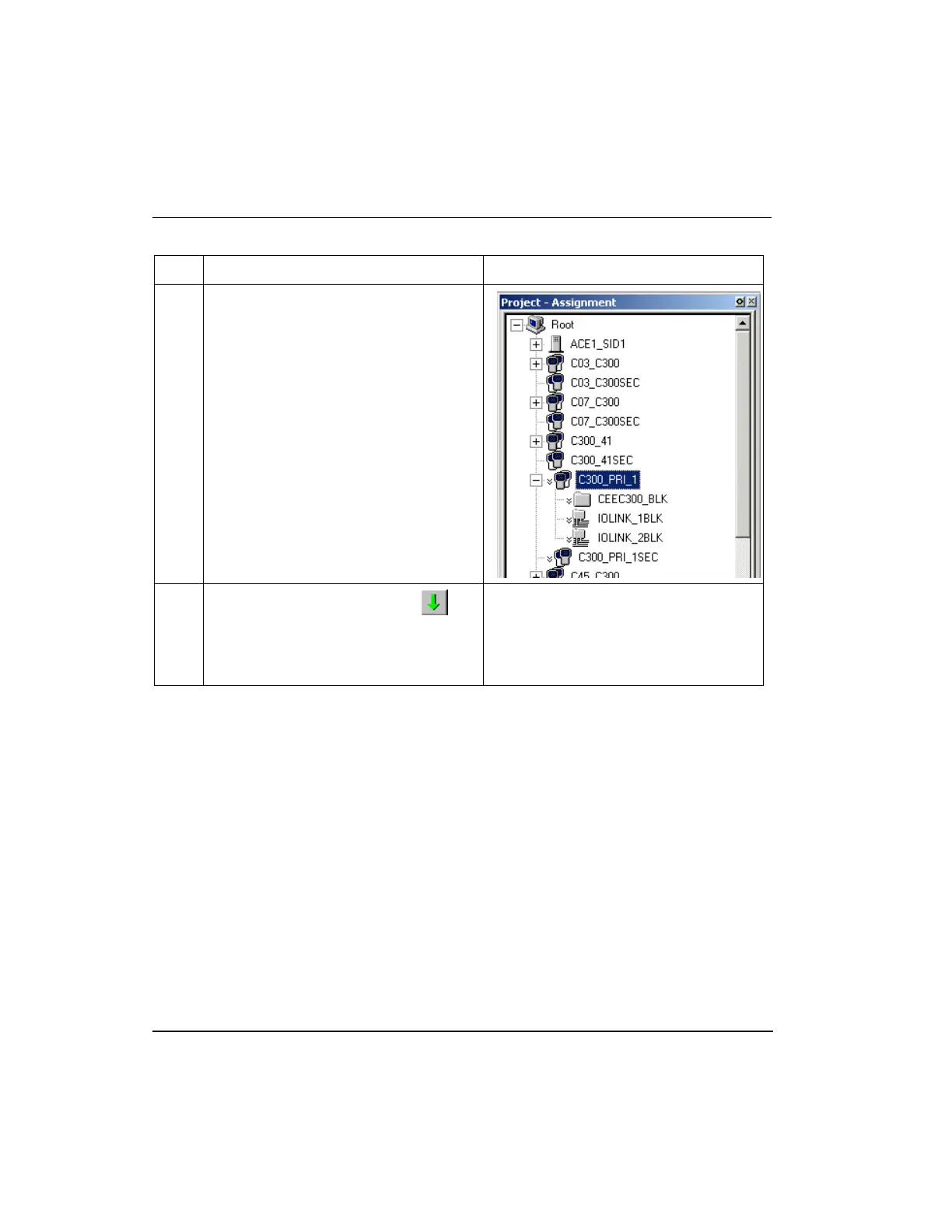
To load a C300 Controller block and its asso
ciated blocks
146
Experion C300 Controller Use
r's Guide
R301.1
Honeywell
11/06
Step Action
Result
tab.
2
Click
Tools->Load
. Or, click t
he
load button in the toolbar.
Also, you can right click on the C300
block icon to select Load.
Calls up Load Dialog b
ox
161
163
Table of Contents
Default Chapter
7
Table of Contents
7
About this Guide
17
Introduction
17
Intended Audience
17
Prerequisite Skills
17
Online Documentation Reference
17
Locating Related Documentation
18
C300 Controller Purpose
19
C300 Controller and C200 Controller Comparison
19
Getting Started
21
What Task Do You Want to Perform
21
C300 Controller Planning and Design
23
Review Experion System Capabilities
23
Control Hardware Planning Guide
23
Series C Control Hardware
24
Series C Form Factor
24
Figure 1 Series C Form Factor Example
25
C300 Controller
26
C300 Controller Execution Environments
27
Figure 2 Redundant C300 Controller Block in the Project Tree
27
I/O Modules Supported by the C300 Controller
28
Table 1 Series a I/O Modules Supported by C300 Controller
28
Identify C300 Controller Components
29
Table 2 Series C Hardware Components
29
C300 Controller Performance Data
31
Control Network Considerations
32
C300 Interface to C200 Controllers and Controlnet Using FTEB
32
C300 Peer Communication with Experion Nodes
32
C300 Connections with Rockwell PLC Devices
33
C300 Connections to the Control Firewall
33
C300 Controller Installation and Upgrades
35
Pre-Installation Considerations
35
Installation Declarations
35
Series C Control Hardware Installation Requirements
36
Series C Power System
36
Controller Memory Backup
37
C300 Controller Installation
37
C300 Controller Assembly
37
Figure 3 C300 Controller IOTA Board Features
38
Table 3 C300 Controller IOTA Board Connector Summary
39
To Install a C300 Controller
40
C300 Secondary Controller Installation
43
To Install a Partner Secondary C300 Controller
44
CF9 Control Firewall
46
9-Port Control Firewall (CF9)
46
Series C I/O Modules Installation
47
Series C FIM Installation
47
Upgrading C300 Controller Firmware
47
Using the Controller Migration Wizard
47
C300 Controller Behavior During Firmware Upgrade and Timeout
47
C300 Controller Configuration
49
Configuration Overview
50
Configuration Studio
50
Define and Add Assets in Your Enterprise Model
50
FTE System Configuration
50
Specifying a Time Server
51
C300 Controller Device Index
51
Create C300 Controller and CEE Function Blocks
52
To Configure a C300 Controller Block
52
Configure CEEC300 Block
58
To Configure a CEEC300 Function Block
58
Configure a Secondary C300 Controller Block
62
To Configure a Secondary C300 Controller Block
63
Convert a Non-Redundant C300 Controller to a Redundant Controller
65
To Convert a Non-Redundant C300 Controller to a Redundant Controller
65
Convert a Redundant C300 Controller to a Non-Redundant Controller
67
To Convert a Redundant C300 Controller to a Non-Redundant Controller
67
Configure IOLINK Function Blocks
68
To Configure IOLINK Blocks
69
Import/Export C300 Controller Configuration
71
Reset Device Index and IP Address of a Controller
71
Create a Control Module
73
To Create and Save a Control Module
74
Assign Control Modules and Ioms to a CEEC300 Block
76
To Assign Control Modules and Ioms to a CEE
77
Copy Control Modules
82
To Copy an Existing Control Module
82
Assign I/O Modules to C300 IOLINK Blocks
84
To Assign Series C IO Modules and Process Manager Ioms to IOLINK Blocks
84
Add an I/O Channel to a Control Module
89
To Add IO Channel Blocks to a Control Module Chart
90
Figure 4 Control Module Chart with an AICHANNEL Block
91
C300 Configuration Form Reference
93
C300 Controller Block
93
Main Tab
93
Redundancy Tab
95
System Time Tab
98
Statistics Tab
100
Peer Connections Tab
102
Hardware Information Tab
103
FTE Tab
104
UTP/TCP Tab
108
IP/ICMP Tab
111
Soft Failures Tab
114
QVCS Tab
116
Server History Tab
116
Server Displays Tab
118
Control Confirmation Tab
120
Identification Tab
120
Secondary C300 Block
122
Main Tab
122
Redundancy Tab
122
CEEC300 Function Block
122
Peer Configuration Tab
125
Statistics Tab
126
CPU Loading Tab
130
CPU Overruns Tab
130
Memory Tab
131
Peer Communications Tab
133
Display Communications Tab
134
Block Types Info Tab
135
Custom Types Info Tab
136
QVCS Tab
137
Server History Tab
137
Server Displays Tab
137
Control Confirmation Tab
137
Identification Tab
137
IOLINK Block
138
Main Tab
138
Memory Stats Tab
140
Statistics Tab
141
I/O Link Status Tab
149
I/O Status Summary Tab
152
IOTA Summary Tabs
153
QVCS Tab
155
Server History Tab
155
Server Displays Tab
156
Control Confirmation Tab
156
Identification Tab
156
Load C300 Controller Configuration
157
About Load Operations
157
Loaded Versus Project Database Versions
157
Load Initiation and Load Dialog Box
158
Load Action with Compare Parameters Function
159
Load Options for Server History and Server Displays Configuration
159
Figure 5 Sample Load Dialog
159
Initial Load Order Guidelines
160
Table 4 Initial Load Order Guidelines
160
Component Deletion Considerations
161
Load Components from Project
161
Loading C300 Controller
161
To Load a C300 Controller Block and Its Associated Blocks
161
Loading IOLINK
164
To Load a IOLINK Block
165
Loading CEEC300
167
To Load a CEEC300 Block
167
Loading Ioms and Cms
169
Load with Contents Command
170
Reloading Components from Project
170
Upload to the Monitoring Database
172
C300 Controller Start up
173
Table 5 C300 Controller Startup and Power on Self Test Routine
174
C300 Controller States in Boot Mode
176
Table 6 Controller in Boot Mode
176
Figure 6 C300 Controller Startup and Boot Mode Indications
176
C300 Controller States in Application Mode
177
Table 7 C300 Controller in Application Mode
177
C300 Controller Operation
173
C300 Faceplate Indicators/Displays
178
Power and Status Leds
179
Table 8 C300 Controller LED Indications
179
Figure 7 C300 Controller Faceplate Features
179
Faceplate Display Information
180
Table 9 C300 Controller Faceplate Display Indications
181
FTE Activity Leds
182
Table 10 FTE Activity LED Indications
182
C300 Faceplate Display Indications
183
Table 11 Display Indications When Controller Is in Application Mode
183
Control Builder Block Icon Descriptions
184
Table 12 Display Indications When Controller Is in Boot Mode
184
Table 13 C300 Controller Icon Indications in Control Builder
185
Activate C300 Controller's CEE
188
Initial Activation Order Guidelines
188
Activating the CEE
188
Setting the CEE Inactive
190
CEE Icon States in the Monitoring Tab
192
Initiating C300 Controller Shutdown
192
Initiating Synchronization Command
193
Prerequisites
193
Commanding Synchronization
193
Disable Synchronization Command
194
Prerequisites
194
To Disable Synchronization
194
Initiating Become Primary Command
194
Commanding Become Primary
195
Initiating Switchover Command
195
Prerequisites
195
Commanding a Switchover
195
Using Station Displays
196
C300 Controller Point Detail Displays
196
Controller Detail Displays
196
Event and Alarm Summary Displays
196
FTE Status Display
196
Viewing Controller Operation and Status in Control Builder
197
Figure 8 Control Builder Monitoring Tab
197
Figure 9 C300 Controller Configuration Form
198
C300 Operating Behaviors
199
Time Management in the C300 Controller
199
Hardware Watchdog Timer
200
Critical Task Health Monitor
200
C300 Controller Overload Conditions
201
C300 Redundancy Operation
203
Description
203
Redundancy Configuration Restrictions
204
C300 Controller Device Index
204
IOLINK Interface Considerations
204
Series C FIM Restrictions
204
Partner (Controller) Compatibility
205
Redundancy Compatibility Parameter - RDNCMPT
206
Synchronization States
207
Standby State
208
Figure 10 C300 Controller Synchronization States
208
Redundancy Parameters
209
Figure 11 C300 Controller Block Redundancy Tab
209
Enable Synchronization - ENBLSYNCCMD
210
Disable Synchronization - DSBLSYNCCMD
210
Enable Standby - ENBLSTBYCMD
210
Auto-Synchronization State - RDNAUTOSYNC
210
Inhibit Sync Reason - RDNINHIBITSYNC
211
Initial Sync Progress - RDNSYNCPROG
212
Maximum Initial Synchronization Time - RDNISTIMEMAX
212
Last Synchronization Time - SYNCTIMEBEG
213
Last Lost of Sync Time - SYNCTIMEEND
213
Redundancy Traffic
213
Redundancy Delay
213
Conditions that Result in Loss of Sync
213
Conditions that Do Not Result in Loss of Sync
214
Switchover
214
Initiate Switchover - SWITCHCMD
214
Max Switchover Time - RDNSOTIMEMAX
214
Conditions that Result in Switchover
215
Conditions that Do Not Result in a Switchover
215
Become Primary Command - BECMPRICMD
216
Redundancy History
216
C300 Redundancy-Related Notifications
216
Table 14 Redundancy-Related Notifications
217
Redundancy Link Status - RDNLINKFAILED
220
OPM Status - RDNOPMSTATUS
220
Table 15 OPM-Related Notifications
220
On-Process Migration of C300 Controller
224
Go-Back to Idle' Option
224
Controller Redundancy Specifications
225
C300 Controller Module and IOTA Replacement
227
To Replace a Non-Redundant Controller Module
227
To Replace a Redundant or Secondary Controller Module
228
To Replace a Non-Redundant Controller IOTA Board
229
To Replace a Redundant or Secondary Controller IOTA
230
C300 Controller Maintenance
227
C300 Controller Troubleshooting
233
Overview
233
What to Do When Faults Occur
233
Initial Checks
234
Checking Control Builder Error Code Reference
234
Checking Faceplate Display and Leds
234
Using Ctools to Capture Diagnostic Data
235
Viewing Flash Log
236
Viewing Release Information Log
236
Checking Server Point Build Log
236
Checking Server Point Build Error Log
236
Checking Error Log
236
Fixing Common Problems
236
Loss of Power
237
Power-On Self Test (POST) Does Not Complete
237
Controller Display Shows -Bp- or -Ts
238
Controller Display Shows -SF- Alternating with OK/BKUP
238
One or both FTE Leds Are RED
239
Controller Does Not Synchronize with Backup
240
Fatal ECC Error
241
Display Shows FAIL
242
Isolated (Lonely) Node
242
Duplicate Device Index Setting
243
Device Index Value Is Zero Upon Power up
244
C300 Controller Soft Failures
244
Table 16 C300 Controller Soft Failures
245
Figure 12 Soft Failures Tab in Control Builder
245
IOLINK Block Soft Failures
248
Table 17 IOLINK Block Soft Failures
248
Additional Status and Fault Messages
251
Redundancy-Related Notifications
251
OPM-Related Notifications - RDNOPMSTATUS Parmaeter
251
Online Diagnostics
251
Fault Classifications
251
Table 18 C300 Fault Classifications and Possible Causes
252
Hard/Severe Failures
253
Soft Failures
254
Installation-Startup Failures
255
Hardware Watchdog Timer Expired
255
Communications Faults
256
Communication and System Time Startup Fault Scenarios
256
Non-Redundant C300 Controller with no Memory Retention
256
Non-Redundant C300 Controller with Memory Retention
258
Redundant Primary C300 Controller with no Memory Retention
259
Redundant Primary C300 Controller with Memory Retention
261
Secondary C300 Controller with no Memory Retention
262
Secondary C300 Controller with Memory Retention
264
Notes
265
Gathering Information for Reporting Problems to Honeywell
266
Getting Further Assistance
267
Other Troubleshooting Sources
267
Guidelines for Requesting Support
269
4
Based on 1 rating
Ask a question
Give review
Questions and Answers:
Need help?
Do you have a question about the Honeywell Experion C300 and is the answer not in the manual?
Ask a question
Honeywell Experion C300 Specifications
General
Brand
Honeywell
Model
Experion C300
Category
Controller
Language
English
Related product manuals
Honeywell C300
285 pages
Honeywell Excel 50
72 pages
Honeywell Excel 15
8 pages
Honeywell EXCEL 10
10 pages
Honeywell Excel 100C
50 pages
Honeywell Excel 10 W7752D
68 pages
Honeywell Excel 10 W7751H
12 pages
Honeywell Excel 800 SYSTEM
92 pages
Honeywell Excel Web XL1000A
10 pages
Honeywell Enraf
78 pages
Honeywell Centra Line EAGLE
30 pages
CENTRA LINE EAGLEHAWK NX
56 pages