I
-
Making Measurements
Measuring Impedance Magnitude
How
the
Transmission
Measurement
Works
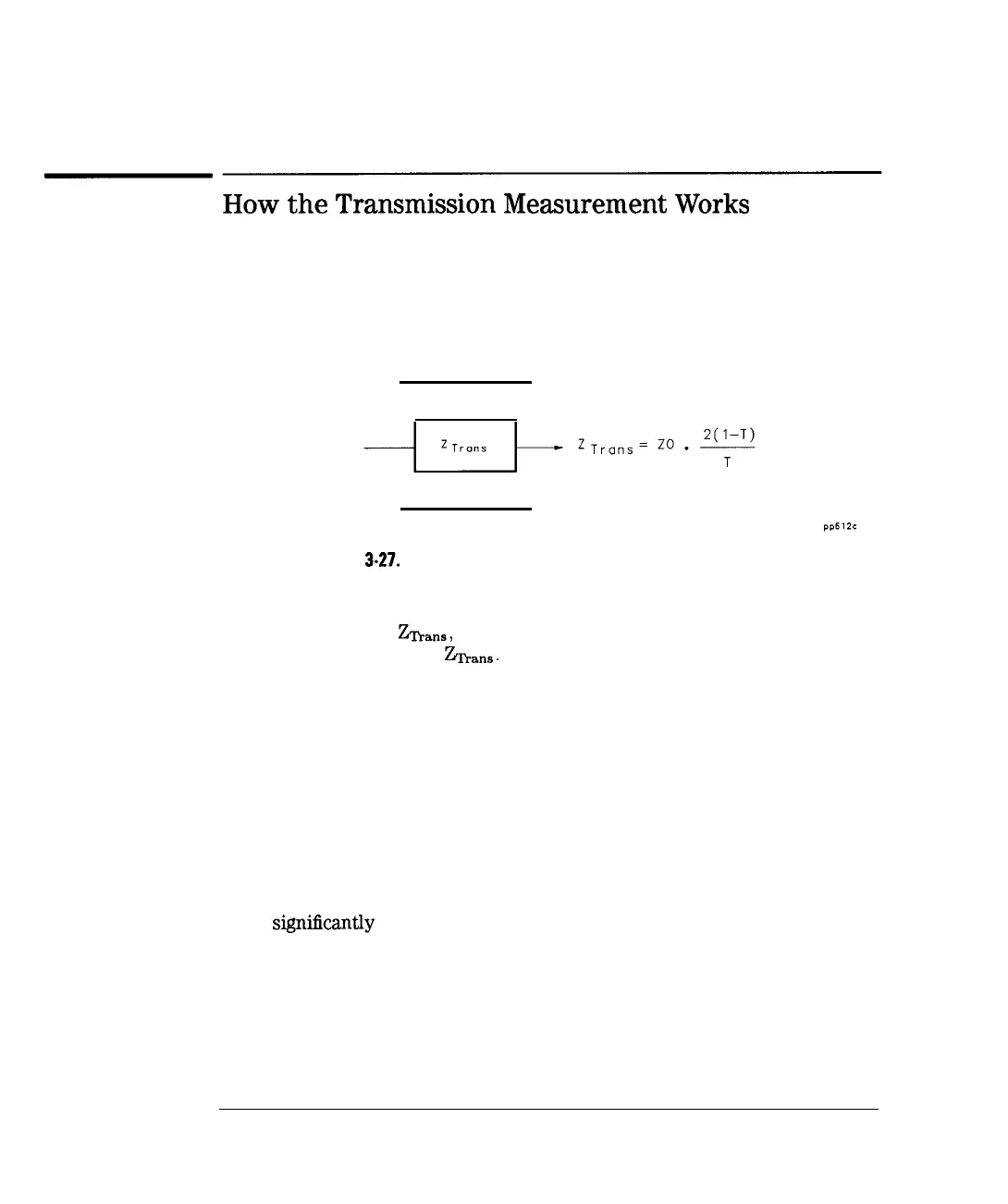
In a transmission measurement, the data can be converted to its equivalent
mathematical series impedance using the model and equations shown in
Figure 3-27.
Transmission (T)
Figure 3-27. Impedance Calculation for Transmission Measurements
In the formula shown above, T is the complex transmission response. The
complex impedance,
Znans,
is computed based on T and ZO. The analyzer
displays the magnitude of
k,,,.
This is not the same as a two-port Z
parameter conversion, as only the measured parameter is used in the
equations.
Since the transmission response calibration cannot correct for source and load
match errors, the results of the transmission transform are less accurate than
the reflection transform. To minimize these errors, a good source match and
load match are required. One way to achieve this is to use pads on both sides
of the device. Be sure to connect the pads before performing the calibration.
When interpreting the resulting impedance measurement, remember that
the analyzer is computing a transform and displaying the equivalent series
impedance. If your device has significant shunt impedance, the results may
differ
signihcantly
from the expected series impedance.
3-64
-1