I
-
Calibrating for Increased Measurement
Accuracy
Check the Calibration
3. Plot the results to disk or to hard copy for later comparison.
4. Compare subsequent calibration checks against the initial one and keep
track of the time interval between the first calibration check and later
ones.
5. When the residual errors have drifted beyond what is acceptable, note
the time interval and use that information to determine what is the best
calibration interval for your measurements.
6. Repeat the process above enough times to feel confident that your
calibration interval is correct.
To
Perform
a
Calibration
Check
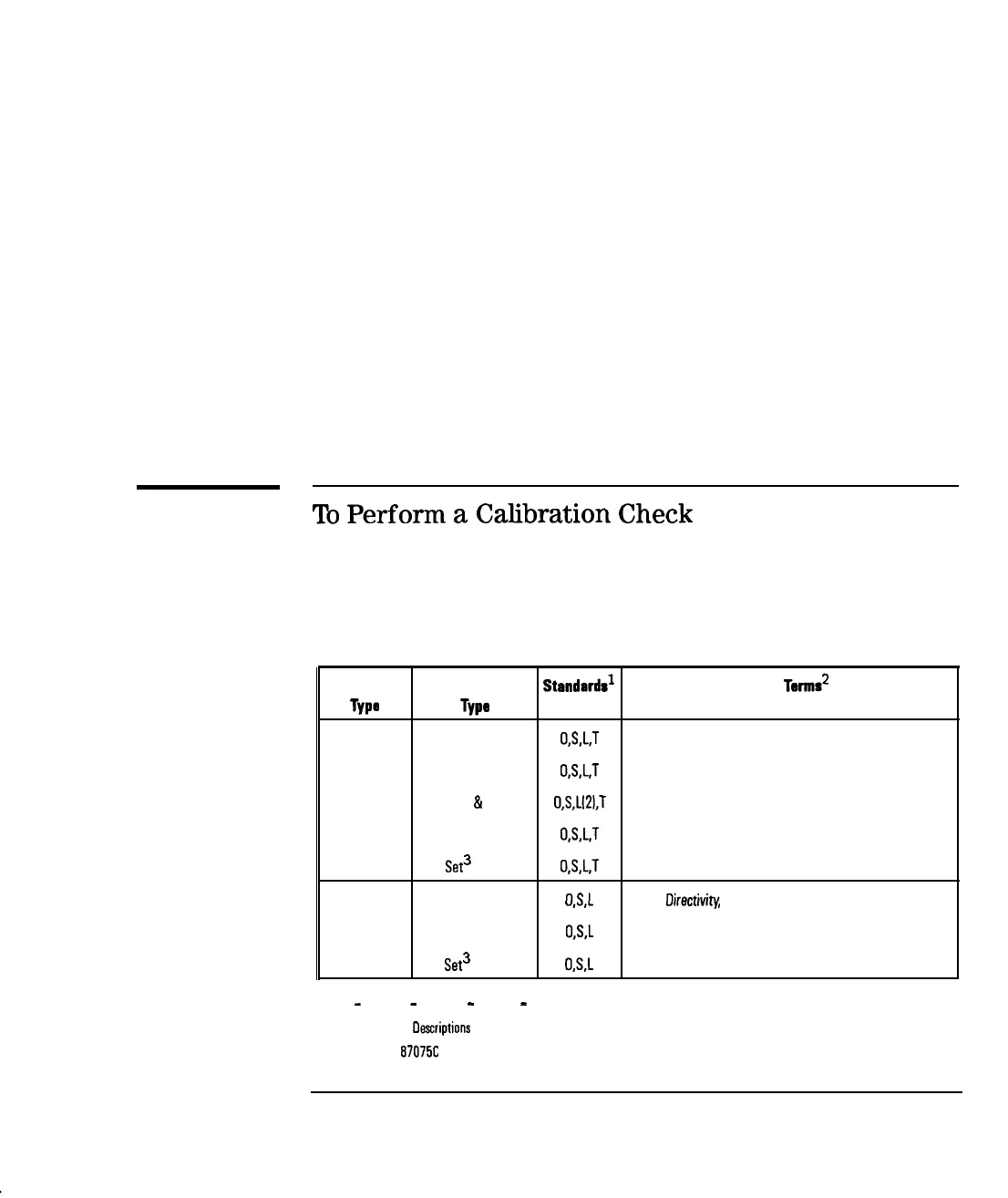
The calibration check feature can be used on any of the transmission or
reflection calibrations available (including the factory default calibration). See
Table 6-2.
Table 6-2. Calibration Check Error Terms
Meesurement Celibretion
Stondordr’
Error
Terms2
Type
TYPO
Needed
Computed
Transmission Default
O,S,L,T
Source Match, Load Match, Transmission Tracking
Response
O.S,L,T
Source Match, Load Match, Transmission Tracking
Response
&
Isolation
O,S,Ll2l,T
Source Match, load Match, Transmission Tracking, lsolatio
Enhanced Response
O,S,L,T
Source Match, load Match, Transmission Tracking
Test
Set3
O,S,L,T
Source Match, Load Match, Transmission Tracking
Reflection
Default
OS,L
Diractivity, Source Match, Reflection Tracking
One Port
O,S,L
Directivity, Source Match, Reflection Tracking
Test
Set3
OS,L
Directivity, Source Match, Reflection Tracking
n
1 0
-
Open, S
-
Short, L
-
Load, T
-
Thru
2 See ‘Error Term
Oascriptions
and Typical Values”, later in this chapter.
3 Used with HP
87075C
multiport test set only
6-27
-1