I
-
I
-
Making Measurements
Measuring Conversion Loss
View
and
Interpret
the
Conversion
Loss
Results
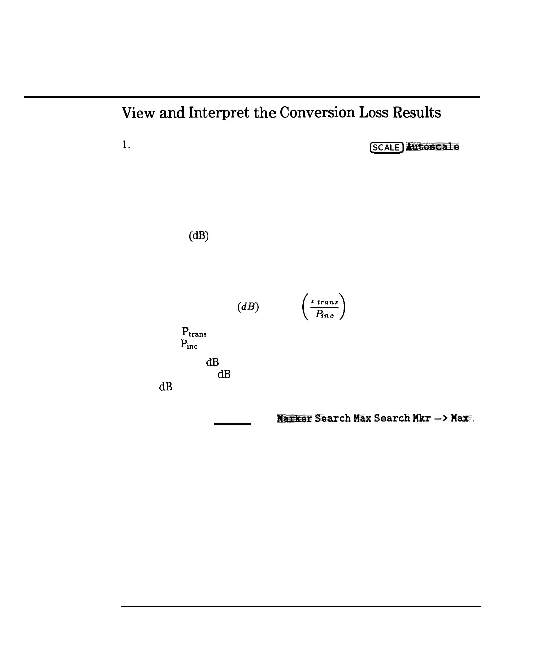
1.
If necessary to view the measurement trace, press
c-1
Au7xjscale
.
2. To interpret the conversion loss measurement, refer to Figure 3-15 or
your analyzer’s display if you are making this measurement on your
instrument.
a. The values shown on the horizontal axis represent the source RF
output. The values shown on the vertical axis are the power ratio in
decibels
(dB)
of the transmitted signal through the device divided by
the incident power. ‘lb display the result in logarithmic magnitude
format (designated by Log Mag at the top of the measurement screen),
the analyzer computes the measurement trace using the following
formula:
P
Conversion Loss
(dB)
= 10 log
F
(
>
*nc
where
Ptrans
=
the power measured at the IF output of the mixer and
where
Pine
= the incident power at the RF input.
b. A level of 0
dR
would indicate a perfect device (no loss or gain). Values
greater than 0
dB
indicate that the mixer has gain. Values less than
0
dR
indicate mixer conversion loss.
3. If you wish, you can quickly determine the mixer’s minimum conversion
loss by pressing [MARKER) Marker Ssaxxh
Nax:
SCWX~
Hkx”
--)
Max.
3-40