I
-
I
-
Specifications and Characteristics
System
The
specihcations
and characteristics in this section describe the system
Specifications
performance of the analyzer. Specifications are valid after the analyzer
has been turned on and allowed to warm up for at least one hour. The
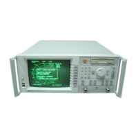
system is defined as the network analyzer itself (which includes a built-in
transmission/reflection test set) and the following:
A calibration kit
-
either
HP
850323 (50
fl)
or HP 850363 (75
Q)
A test port cable
-
either HP part number 8120-6469 (50
Q)
or
HP part number 8120-6468 (75
0)
Specifications describe the instrument’s warranted performance over
the temperature range of
25”
f
5
“C,
unless otherwise stated. These
speci6cations
are valid only after the instrument has been turned on and
allowed to warm-up for at least one hour.
Supplemental characteristics (indicated by italics) are typical, but
nonwarranted parameters, intended to provide information useful in applying
the instrument.
Dynamic
Range
Receiver dynamic range is calculated as the difference between the maximum
receiver input level and the receiver’s noise floor. System dynamic range
applies to transmission narrowband measurements only, since reflection
measurements are limited by directivity.
Noise floor is specified as the mean of the noise trace at
specihed
CW
frequencies. A signal at this level would have a signal/noise power ratio of
3
dEI.
Noise floor is measured with the test ports terminated in loads, response
and isolation calibration, 15 Hz IF bandwidth, 0
dBm
test port power and
no averaging. Dynamic range specifications are listed later in the “Receiver
Spetications”
section of this chapter.
10-2

 Loading...