5 Installation and commissioning
HSD S.p.A. © - h0104k01a.fm120718
103
5.6.1 Hydraulic connection points
To know the position of the connection points on the different versions, refer to the dimensional
drawings (Technical Datasheet) consigned with the product or available upon request from
Customer Service.
For the connection of the rotary fluid distributor (if installed), see paragraph
5.7 “Fluid
distributor connections”
.
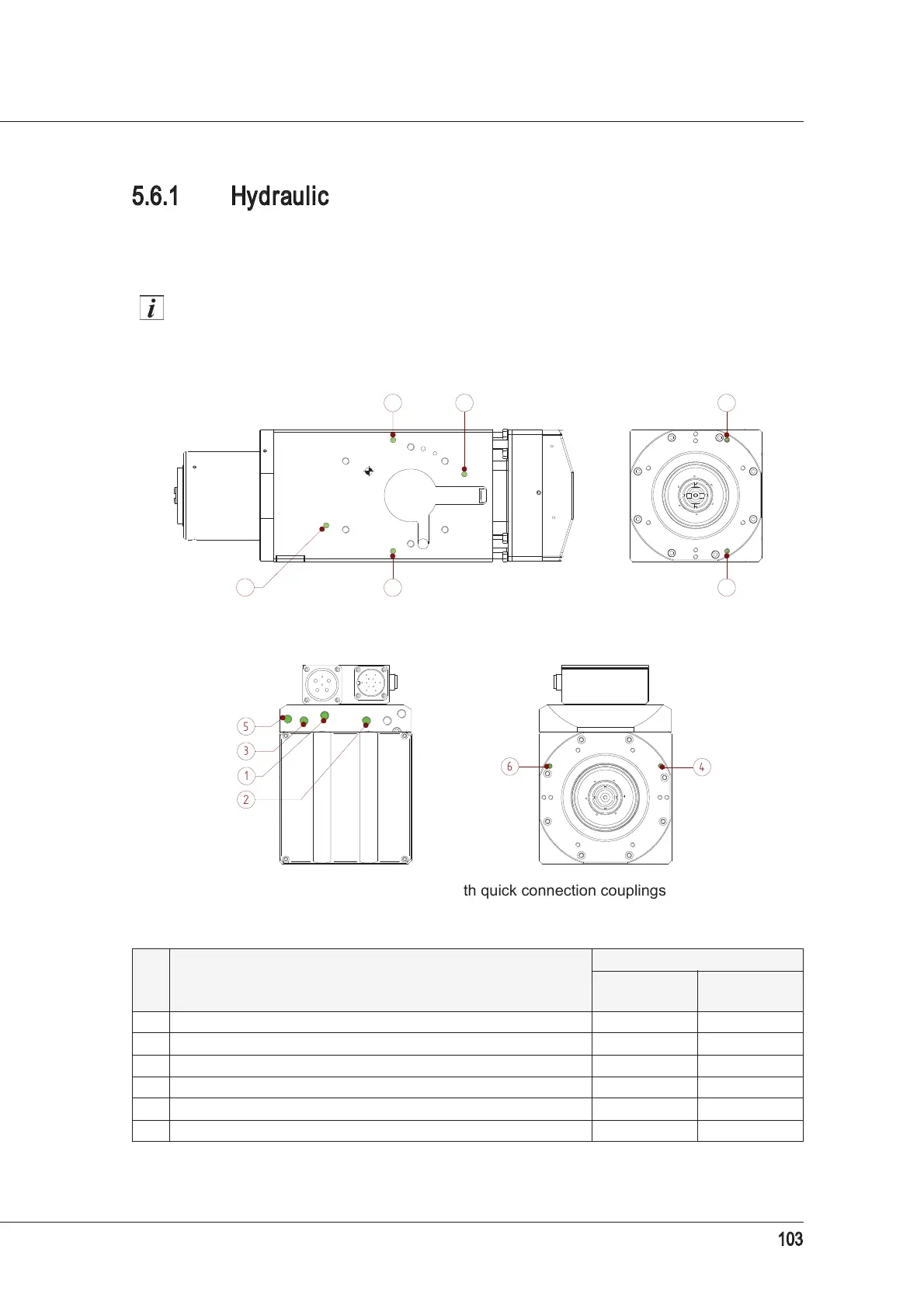
The figures show examples of connection points.
Ref. Description
Bore Ø
on the
surface
for
connectors
1 Motor coolant inlet 6 mm G1/8”*
*
Straight quick connection couplings are supplied for Ø6 mm tubes.
2 Motor coolant outlet 6 mm G1/8”*
3 Lubricant/coolant inlet outside the tool - line “A” 6 mm G1/8”*
4 Lubricant/coolant outlet outside the tool - line “A” M6x8 M6x8
5 Lubricant/coolant inlet outside the tool - line “B” 6 mm G1/8”*
6 Lubricant/coolant outlet outside the tool - line “B” M6x8 M6x8
Example of connections on the support surface (fluid distributor surface)
Example of connections with quick connection couplings