7 Operation and regulation
HSD S.p.A. © - h0106k01a.fm120718
139
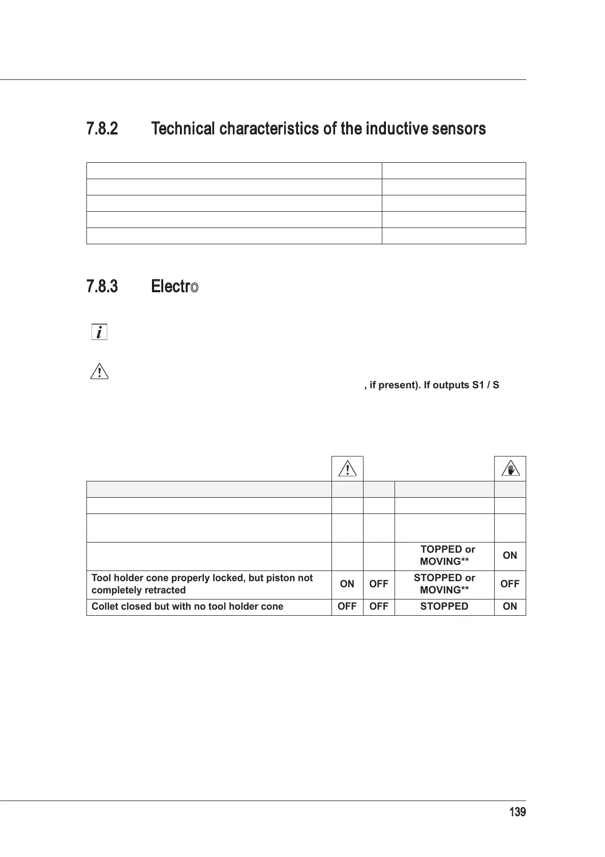
7.8.2 Technical characteristics of the inductive sensors
7.8.3 Electrospindle conditions and corresponding outputs
of the inductive sensors
The sensor “ON” condition corresponds to an output equal to the power supply voltage. The
“OFF” condition corresponds to a 0V output.
The electrospindle shaft can only rotate in the “tool-holder cone correctly locked”
condition, and if the piston is fully backward (S5 ON, if present). If outputs S1 / S1+S4
(HSK versions only) or S5 (if present) change to “OFF”, stop the rotation of the
electrospindle shaft.
Versions with ISO locking system
Proximity PNP type Normally Open (N.O.) S1 / S2 / S3 / S4 / S5
Power supply voltage 10 ÷ 30V (DC)
Maximum load 200 mA
No-load absorption <10 mA
Nominal reading distance 0.8 mm
STATE
S1 S2 S3*
*
Present in certain versions only.
S5*
Collet open (tool holder cone ejected) OFF ON
STOPPED
OFF
Tool holder cone locked correctly ON OFF
STOPPED or
MOVING**
**
Depending on the operational status of the machine.
ON
Tool holder cone not correctly locked
OFF OFF
STOPPED or
MOVING**
ON
Tool holder cone properly locked, but piston not
completely retracted
ON OFF
STOPPED or
MOVING**
OFF
Collet closed but with no tool holder cone OFF OFF
STOPPED
ON