7 Operation and regulation
HSD S.p.A. © - h0106k01a.fm120718
131
5. Use the value X to choose the right curve on the graph.
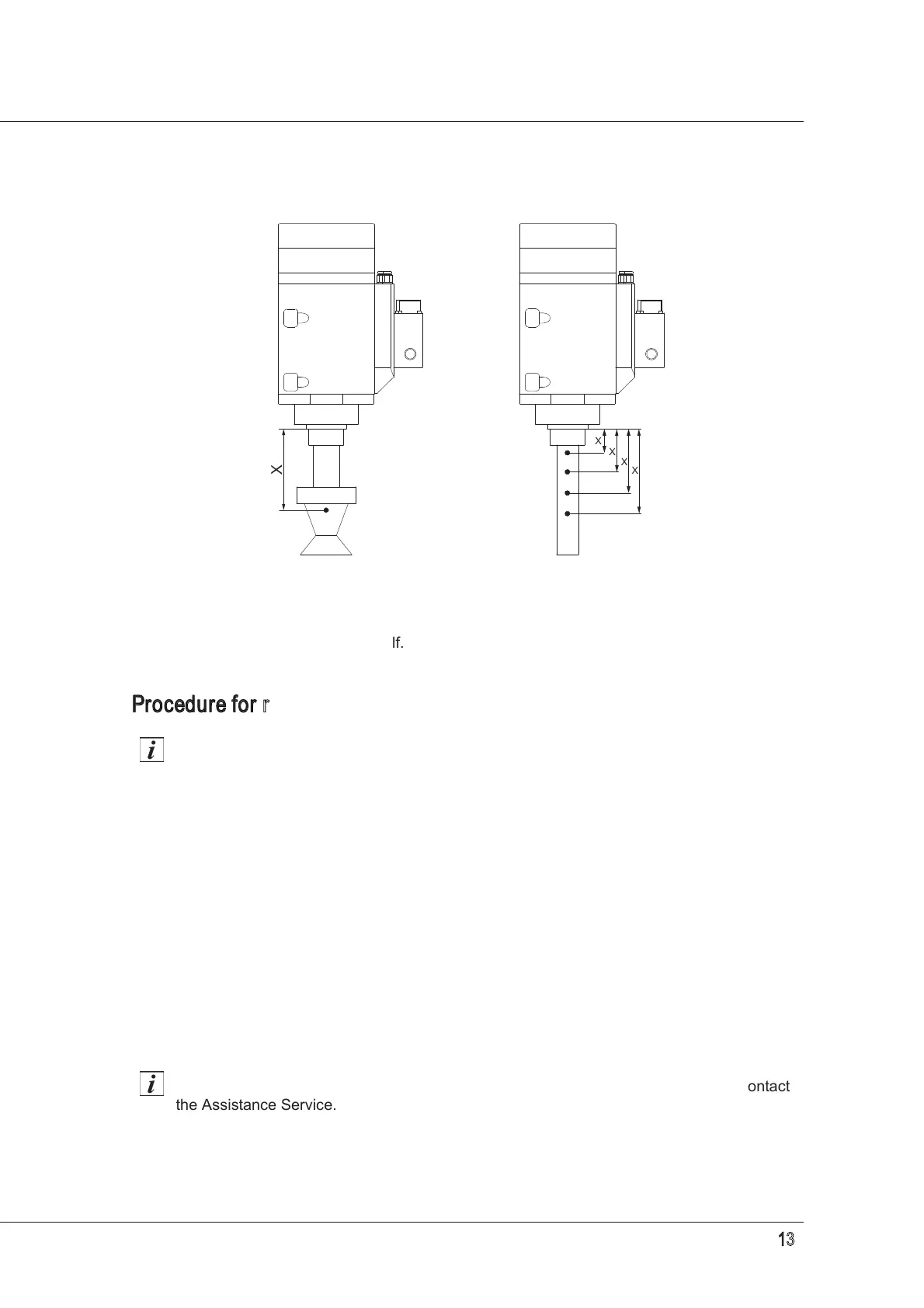
All tools, whatever their shape, can be considered as equivalent to a cylindrical tool (as shown
alongside the graphs on the following pages). From the graphs, select the curve corresponding to
the position of the centre of gravity of the tool in question, then read the maximum number of rpm
according to the weight of the tool itself.
Procedure for reading the graphs
The graphs on the following pages are merely an example, in that they don't take into
account the machining parameters, the specific characteristics of the tool used by the
customer, or the type of material being machined (because the manufacturer cannot be
aware of these factors).
It is the user's responsibility to assess the maximum speed for the safe use of the
tool in each individual situation.
1. Identify the graph relating to the electrospindle in use.
2. Select one of the curves according to the distance "X" between the spindle nose and centre of
gravity "G" of the tool+tool holder assembly. If the value "X" measured on the electrospindle in
use does not appear on the graph, select the curve associated to the next highest "X" (see
example)
3. Read the maximum speed value corresponding to the weight of the tool+tool holder assembly.
4. If the weight or the distance of G is higher than that provided for by the manufacturer, it is the
user's responsibility to evaluate the maximum safe operating speed case by case.
If it is thought that the tool may be too large and could damage the electrospindle, contact
the Assistance Service.