5 Installation and commissioning
98
HSD S.p.A. © - h0104k01a.fm120718
5.5.2 Pneumatic connection points
To know the position of the connection points on the different versions, refer to the dimensional
drawings (Technical Datasheet) consigned with the product or available upon request from
Customer Service.
For the connection of the rotary fluid distributor (if installed), see paragraph
5.7 “Fluid
distributor connections”
.
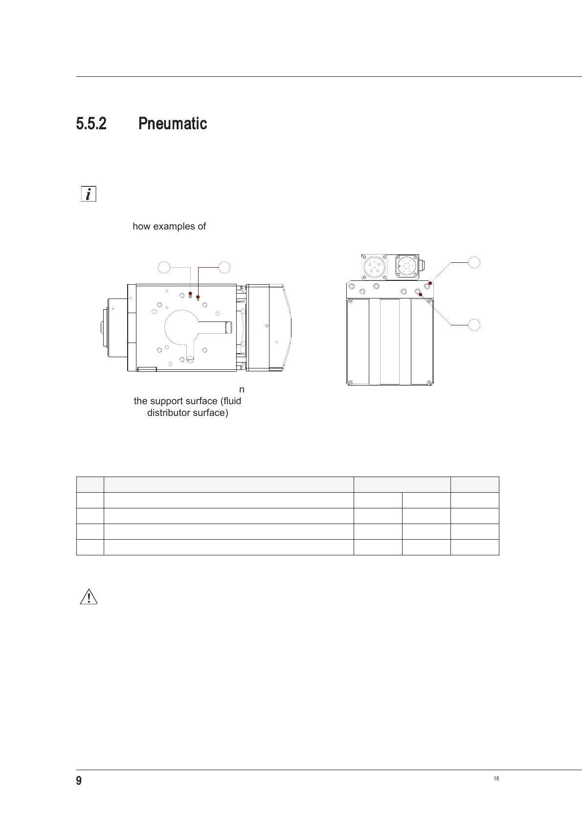
The figures show examples of connection points.
Technical data
The pneumatic supply must never exceed the value stated in the technical data. For
this reason, a pressure regulator must always be fitted on the supply line.
Ref. Description Power supply Bore Ø
1 Air inlet/outlet for tool-holder release (piston forward) 10 bar 145 PSI 5 mm
2 Air inlet for cone cleaning and pressurisation 4 bar 58 PSI 4 mm
3 Air inlet/outlet for tool-holder release (piston forward) 10 bar 145 PSI G1/8”*
*
Straight quick connection couplings are supplied for Ø6 mm tubes.
4 Air inlet for cone cleaning and pressurisation 4 bar 58 PSI G1/8”*
1 2
Example of connections with
quick connection couplings
Example of connections on
the support surface (fluid
distributor surface)