5 Installation and commissioning
HSD S.p.A. © - h0104k01a.fm120718
117
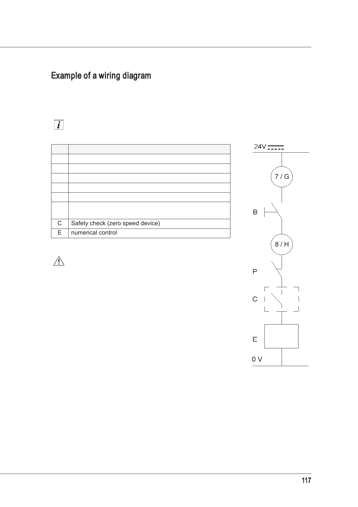
Example of a wiring diagram for manual tool-holder release
The button may be used to manually command the tool-holder release so that, when the button is
kept pressed, the tool is ejected and the collet remains open (optional).
For example, the following diagram shows the connections to be made by the user.
The circuit indicated here is merely an example.
When the spindle is rotating, a control system must
disable the command from the button.
• The button must only be enabled when the spindle is
stopped.
• The tool lock/release operation via the button must only
be carried out with the machine in MANUAL operating
mode (not AUTOMATIC).
• If the above safety requirements are not complied with,
the tool can be ejected violently at high speed.
Ref. Description
7 Pin +24V DC power supply to button, HSD connector
G Pin +24V DC power supply to button, MIL connector
B Tool release button
8 Pin for button output, HSD connector
H Pin for button output, MIL connector
P
Pressure switch that disables the release of the tool holder
if the pressure is too low
C Safety check (zero speed device)
E numerical control
8 / H
7 / G