5 Installation and commissioning
HSD S.p.A. © - h0104k01a.fm120718
115
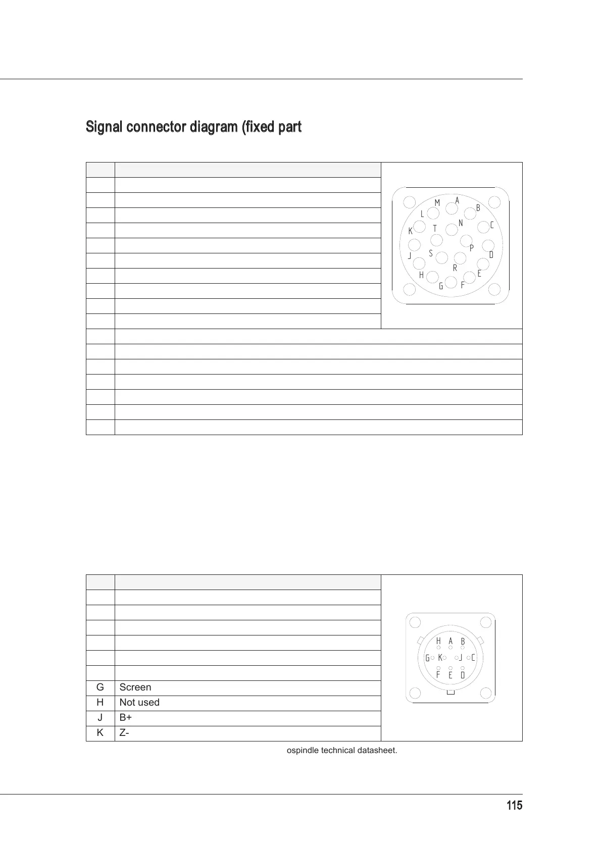
Signal connector diagram (fixed part)
Encoder connector diagram (fixed part)
This connector is only present in versions fitted with an encoder.
PIN DESCRIPTION user side view
A Sensor S2 output
B S1+S4 sensors series Output
C Sensor S3 output*
*
Present in certain versions only.
D +24VDC power supply to S1, S2, S3*
E +24VDC power supply to button indicator light
F 0V power supply to S1, S2, S3*, S4
G +24V
DC power supply to button
H Button output
J 0V power supply to button and indicator light
K Not used
L Not used
M Sensor S1 output
N Depending on the version**: thermal alarm*** or not used.
**
The thermal alarm is connected to the power connector or the signal connector, depending on the version.
***
On the Technical Datasheet, check the type of thermal alarm fitted on your own model.
P Depending on the version**: thermal alarm*** or not used.
R Not used
S Not used
T Not used
PIN DESCRIPTION user side view
A A+
B A-
C B-
D 0V
E Z+
F Electricity supply*
*
For the encoder supply voltage, refer to the electrospindle technical datasheet.
G Screen
H Not used
J B+
K Z-
A
B
D
C
E
G
H
F
J
K
L
M
P
R
S
T
N
B
C
DE
F
G
H
A
K J