9 Replacing components
HSD S.p.A. © - h0108k01a.fm120718
169
9.3 Replacing and adjusting the sensors
The sensors are pre-assembled in calibrated nuts to be easily inserted into the electrospindle at
the correct depth. The various sensors are identifiable by the number listed on the label of the
cablemarker. The sensors are adjusted by rotating them in their seats.
The exchange of sensors damages moving parts.
9.3.1 Identifying and accessing the sensors
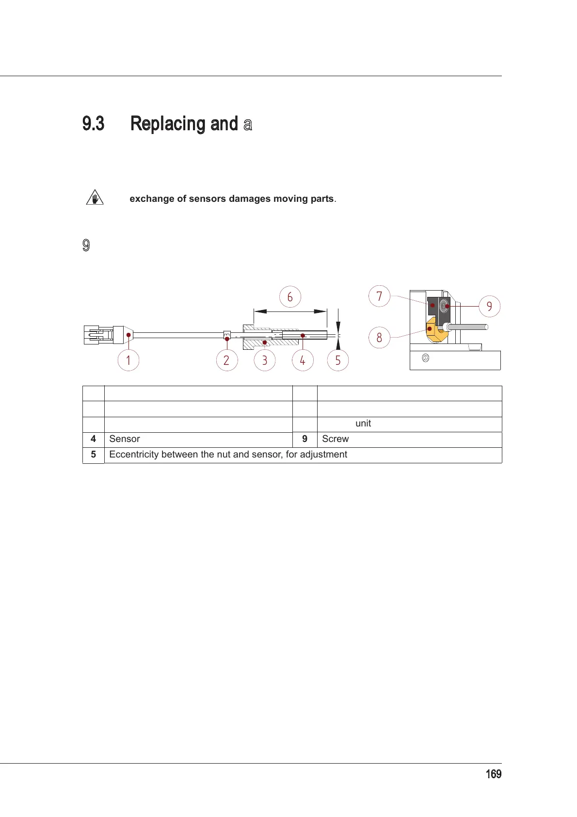
Figure 10: sensor unit Figure 11: sensor connection
1 Electric connector 6 Calibrated position
2 Numbered label 7 Bracket and block
3 Pre-inserted nut 8 Sensor unit
4 Sensor 9 Screw
5 Eccentricity between the nut and sensor, for adjustment