5 Installation and commissioning
HSD S.p.A. © - h0104k01a.fm120718
113
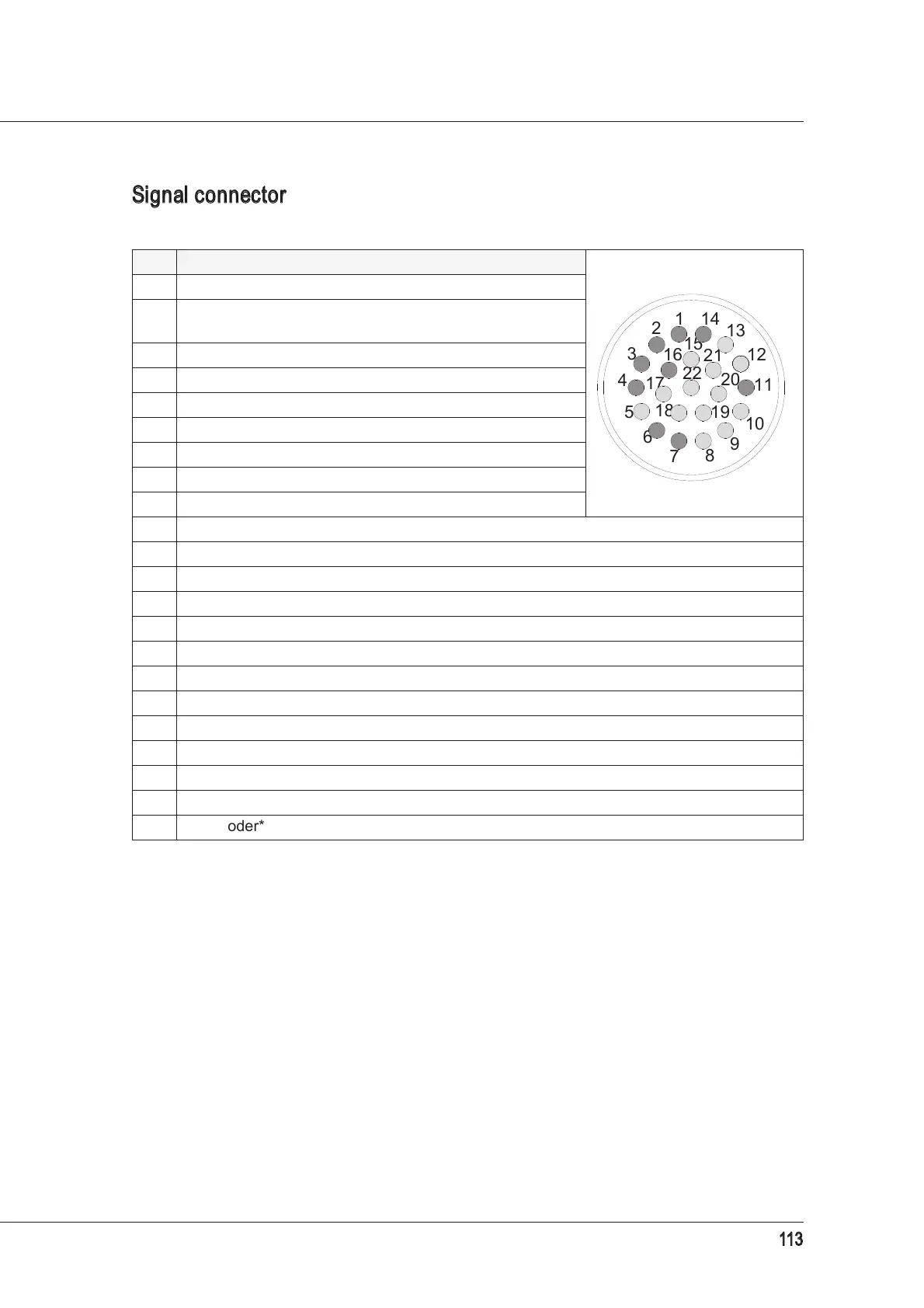
Signal connector diagram (fixed part)
PIN DESCRIPTION user side view
1 Sensor S2 output
2
ISO versions: sensor S1 output
HSK versions: sensor S1+S4 output
3 Sensor S3 output*
*
Present in certain versions only.
4 +24V DC power supply to S1, S2, S3*
5 +24V DC power supply to button indicator light
6 0V power supply to S1, S2, S3*
7 +24V
DC power supply to button
8 Button output
9 Not used
10 Not used
11 0V power supply to button and indicator light
12 Not used
13 Not used
14 For HSK versions only: sensor S1 output
15 A+ encoder*
16 A- encoder*
17 B- encoder*
18 0V encoder*
19 Z+ encoder*
20 Electricity supply** to encoder*
**
For the encoder supply voltage, refer to the electrospindle technical datasheet.
21 B+ encoder*
22 Z- encoder*
7
14
1
2
13
15
12
3
16
8
21
22
20
4
17
11
18
5
19
10
6
9