5 Installation and commissioning
HSD S.p.A. © - h0104k01a.fm120718
99
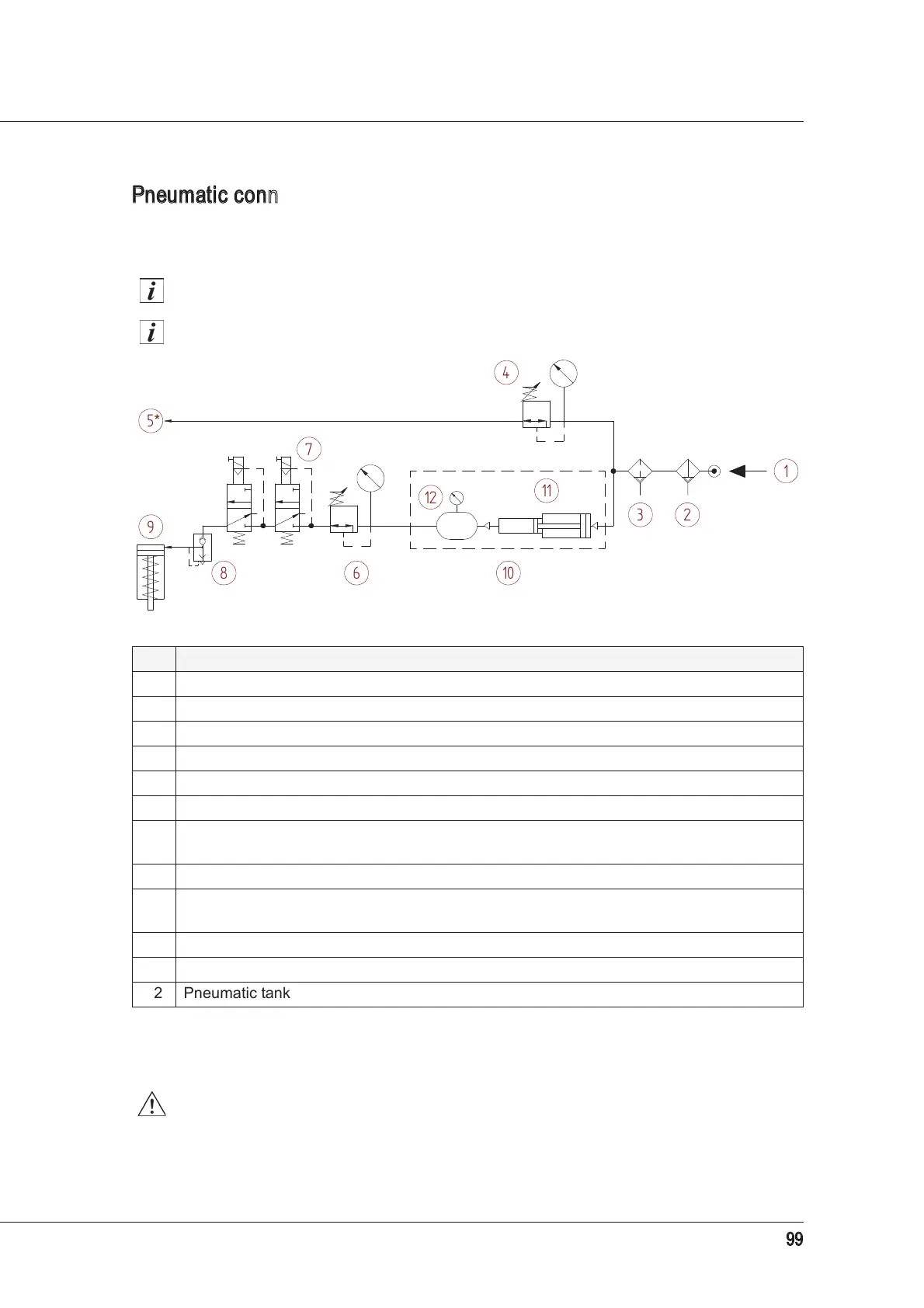
Pneumatic connection examples
For exemplary purposes we have provided the pneumatic connection layout in the figure below,
which should be created by the user.
The minimum diameter of the circuit pipes is 6/4mm.
The circuit indicated here is merely an example.
The use of two solenoid valves in series (instead of one) reduces the risk of
malfunctioning. Even though these malfunctions are quite infrequent, due to their
possible serious nature, the adoption of a redundancy principle is recommended.
Ref. Description
1 Pneumatic circuit supply
2 Pre-filter 5 µm see paragraph
5.5.1
3 Oil separator filter 0.1 µm see paragraph 5.5.1
4 Pressure regulator with pressure switch 4 bar / 58 PSI
5 Air inlet for cone cleaning and pressurisation*
*
This inlet in versions with a rotary fluid distributor only provides pressurisation, whereas automatic cleaning of the
cone is supplied by another circuit connected to the fluid distributor and shown in paragraph
5.7 “Fluid distributor
connections”
.
4 bar / 58 PSI
6 Pressure regulator with pressure switch 10 bar / 145 PSI
7
Pair of 3-way monostable solenoid valves
(use solenoid valves that are suited to the pressures involved)
8 Rapid bleeder valve
9
Air inlet/outlet for tool-holder release
(piston forward)
10 bar / 145 PSI
10 Potential pressure multiplication system
11 Pressure multiplier
12 Pneumatic tank
*