5 Installation and commissioning
112
HSD S.p.A. © - h0104k01a.fm120718
5.8.2 Versions with HSD electrical connectors
The position of the electrical connectors is shown in paragraph 3.4.5 “Variations with HSD electric
connectors”
. The connectors are housed in a junction box, also known as a "fixed mounting plate".
There's also a tool manual release button on the fixed mounting plate; to connect it, refer to
paragraph
5.8.4 “Tool release button”. The electrospindle also has a "mounting plate" with plug
connectors, which must be wired by the customer.
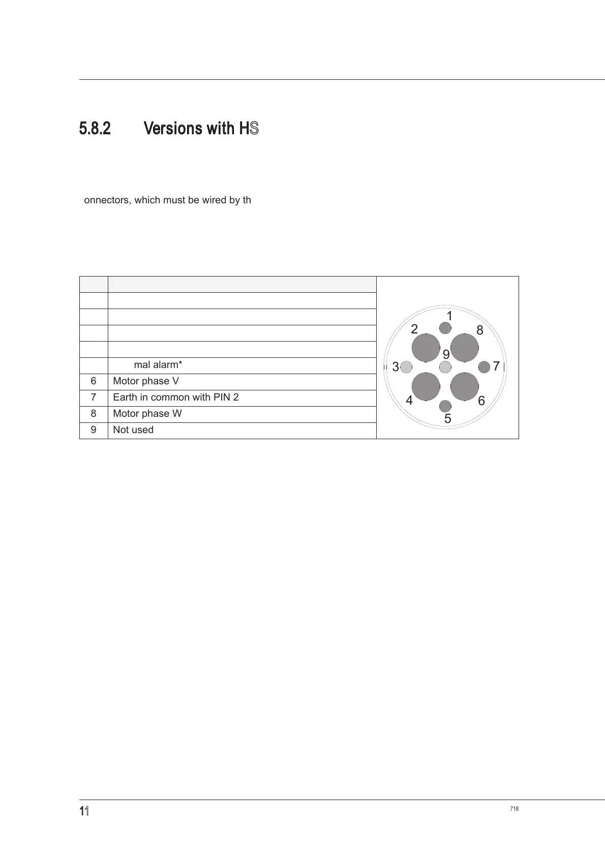
Power connector diagram (fixed part)
PIN DESCRIPTION user side view
1 Thermal alarm*
*
On the Technical Datasheet, check the type of thermal alarm fitted on your own model.
2 EARTHING common with PIN 7
3 Not used
4 Motor phase U
5 Thermal alarm*
6 Motor phase V
7 Earth in common with PIN 2
8 Motor phase W
9 Not used