9 Replacing components
176
HSD S.p.A. © - h0108k01a.fm120718
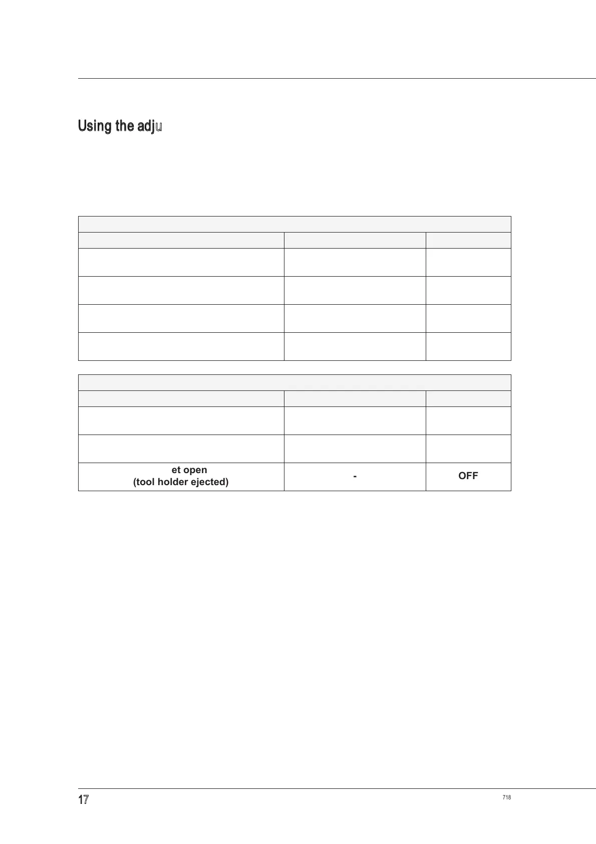
Using the adjustment gauge kit
After replacing the sensor and checking the ejection position as described in paragraph
9.3.2 “Replacing the sensor unit”, adjust the sensor as follows:
1. use the gauge kit as shown in figures
16 to 18, and make sure the sensor signal corresponds
with the relative table below;
2. rotate the shaft manually and check that the table is verified for the entire 360° rotation
;
3. if not, turn the sensor slowly until you find the position in which the output described in the
table is obtained;
4. tighten the screw that fastens the sensor completely;
5. perform a cycle of 10 tool changes;
6. at the end of the cycle, check that the conditions of the relative table have been met for the entire
360° shaft rotation. Otherwise, repeat the procedure from the start
;
7. if the table is verified, make the machine perform a cycle of 100 tool changes, using the largest
possible number of different tool holders;
8. at the end of the cycle, check that the conditions of the table have been met for the entire 360°
shaft rotation. Otherwise, repeat the procedure from the start;
9. if the table conditions have been met, the sensor calibration is complete.
Table for adjusting sensor S1
Condition Adjustment Output S1
gauge locked
(tool holder locked)
S1 reads ON
gauge locked
(tool holder locked)
S1 does not read OFF
no gauge
(collet closed without tool-holder)
- OFF
collet open
(tool holder ejected)
- OFF
Table for adjusting sensor S4
Condition Adjustment Output S4
gauge locked
(tool holder locked)
S4 reads ON
gauge locked
(tool holder locked)
S4 does not read OFF
collet open
(tool holder ejected)
- OFF