7 Operation and regulation
124
HSD S.p.A. © - h0106k01a.fm120718
The electrospindle must not be started without the tool holder inserted.
During machining, the spindle can reach high temperatures so it must not be
touched without taking due precautions.
7.4 Tool-holder locking and ejection device
The ejection of the tool holder occurs via the movement of a pneumatic piston, operated by
compressed air. For the piston characteristics, refer to paragraph
5.5.3 “Pneumatic cylinder”.
The tool holder is locked mechanically by elastic springs.
The axial force exerted on the tool-holder by the locking system is guaranteed constant for a
minimum duration of 2,000,000 tool change cycles.
1 Tool Change Cycle = Tool Locked / Tool Released / Tool Locked.
The axial force exerted on the tool holder by the locking system must never drop
below 70% of the minimum value. Dropping below this level means exposure to
serious danger for the operator as well as the risk of damaging the product.
The tool ejection and change operations must take place with the shaft stopped.
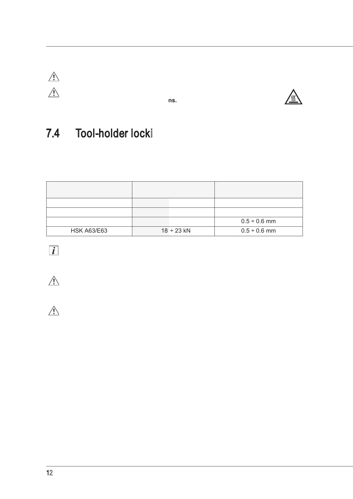
Tool-holder connection
device type
Axial force on the tool-
holder
Tool-holder cone ejection
ISO 30
2.9 ÷ 3.5 kN 0.5 ÷ 0.9 mm
HSK E40/F50
6.8 ÷ 9.5 kN 0.5 ÷ 0.6 mm
HSK F63
11 ÷ 14 kN 0.5 ÷ 0.6 mm
HSK A63/E63
18 ÷ 23 kN 0.5 ÷ 0.6 mm