9 Replacing components
178
HSD S.p.A. © - h0108k01a.fm120718
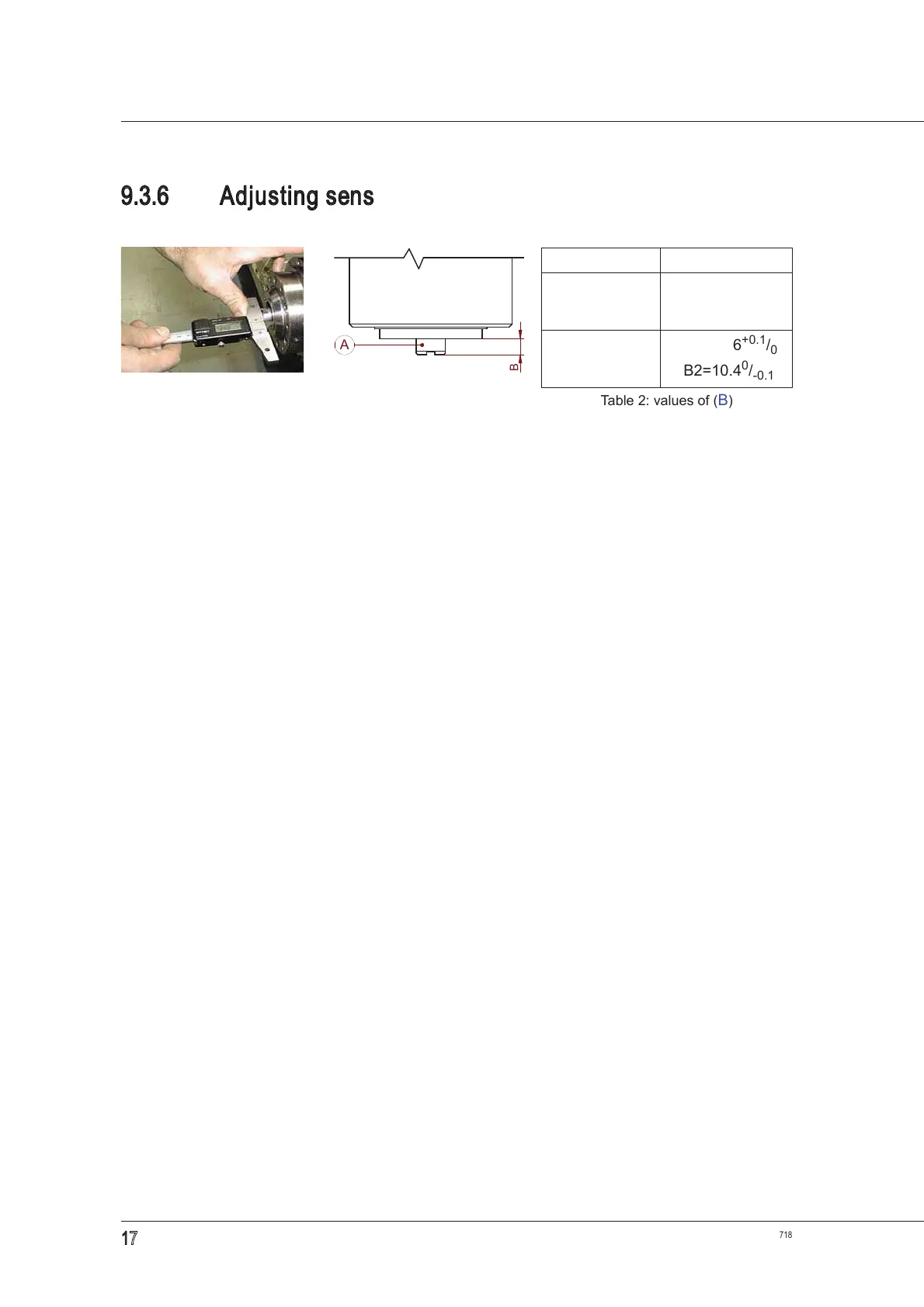
9.3.6 Adjusting sensor S2 for HSK versions
After replacing the sensor as described in paragraph 9.3.2 “Replacing the sensor unit”, calibrate it
as follows:
1. bring the spindle to the
“Collet open (tool-holder cone ejected)” condition, where the piston is
forward and the position (B) (figure
20) assumes the maximum value;
2. as shown in figures 19 and 20, use a depth gauge to check that position (B) of the ejector in
relation to the spindle nose assumes the value B1 indicated in table
2;
if this is not the case, make the adjustment described in paragraph
7.4.1 “Checking and
adjusting the HSK collet ejection position”
before adjusting the sensor;
3. bring the piston backward so the position (B) assumes the minimum value;
4. feed the cylinder by means of a unidirectional pressure regulator, set initially at 0 bar (0 PSI);
5. increase the pressure with 0.1 bar steps (1.5 PSI), in order to make the ejector move slowly;
6. stop when the position (B) reaches value B2;
7. rotate sensor S2 until you find the position that provides the
“ON” signal with (
B) > B2 and the
“OFF” signal with (
B) < B2;
8. tighten the screw that fastens the sensor completely;
9. perform a cycle of 10 tool changes;
10. at the end of the cycle, check that point [7] is met
without needing to move the sensor
;
11. if necessary, move the sensor and then repeat the entire procedure from the beginning;
12. if not necessary move the sensor, then make the machine perform a cycle of 100 tool
changes, using the largest possible number of different tool holders;
13. at the end of the cycle, check that point [7] is met
without needing to move the sensor
;
14. if necessary move the sensor, then repeat the entire process from the beginning;
15.
if it is not necessary
to move the sensor,
then
the S2 adjustment process is complete.
Figure 19: ejector position Figure 20: (A) ejector
(B) reference position
HSK form
B
(mm)
A40, E40, F50
B1=8.6
+0.1
/
0
B2=8.4
0
/
-0.1
A63, E63, F63
B1=10.6
+0.1
/
0
B2=10.4
0
/
-0.1
Table 2: values of (B)