NOTE
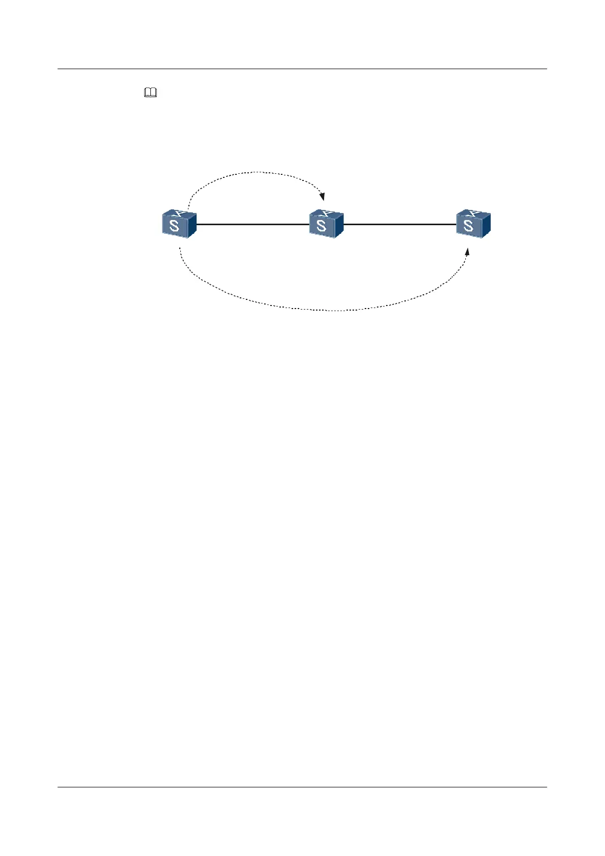
For convenience, only four devices in the Layer 2 network are described.
Figure 3-3 Networking diagram of configuring basic HGMP functions for a cluster
SwitchC
SwitchB
test2
GE0/0/1
VLANIF110
10.1.1.1/24
GE0/0/1
VLANIF110
10.1.1.2/24
GE0/0/1
VLANIF120
10.2.1.2/24
GE0/0/2
VLANIF120
10.2.1.1/24
test1
SwitchA
Device MAC address Device MAC address
Administrator-1 0001-0001-0001 Member-1 0002-0002-0002
Member-2 0003-0003-0003 Member-3 0004-0004-0004
Configuration Roadmap
The configuration roadmap is as follows:
1. Create a management VLAN on all devices. Enable NDP and NTDP to ensure that each
device can detect the topology structure of the network through NTDP.
2. Choose the administrator switch, and then create a cluster named HUAWEI on the
administrator switch.
3. Add all the devices that support HGMP in the Layer 2 network to the cluster.
4. Assign an IP address to VLANIF 10 to facilitate the communication between member
switches in the cluster and devices out of the cluster.
5. Configure public servers and hosts for the cluster.
Data Preparation
To complete the configuration, you need the following data:
l Management VLAN ID of the cluster, that is 10
l IP address of VLANIF 10, that is 1.0.0.1/8
l Address pool of the cluster, that is 10.0.0.0/8
l IP address of the administrator in the cluster, that is 10.0.0.1/8
l MAC addresses of devices, as shown in Figure 3-3
l IP addresses of servers and hosts, as shown in Figure 3-3
Quidway S5700 Series Ethernet Switches
Configuration Guide - Network Management 3 HGMP Configuration
Issue 01 (2011-10-26) Huawei Proprietary and Confidential
Copyright © Huawei Technologies Co., Ltd.
110

 Loading...