EasyManuals Logo

IDEC SMARTRELAY User Manual

IDEC SMARTRELAY
338 pages
To Next Page IconTo Next Page
To Previous Page IconTo Previous Page
Page #16 background imageLoading...
Page #16 background image
Getting started with IDEC SmartRelay
IDEC SmartRelay Manual
4
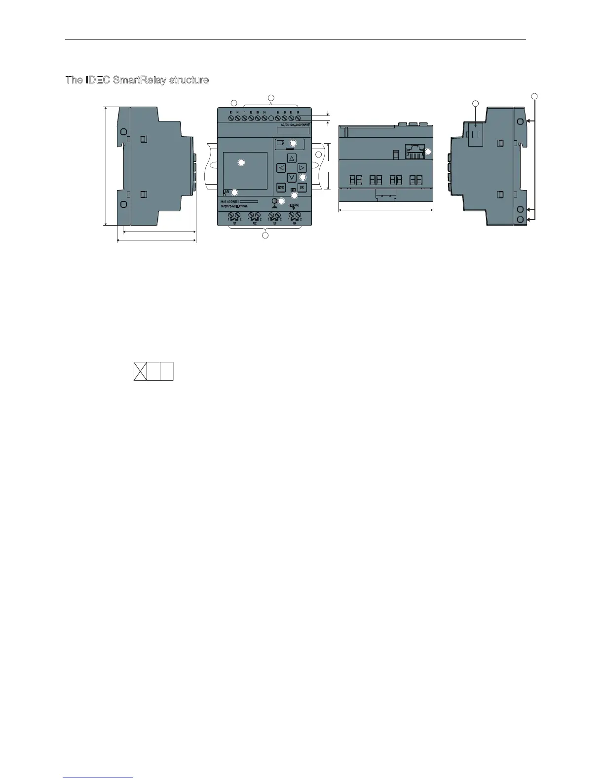
The IDEC SmartRelay structure
Power supply
Inputs
Outputs
FE terminal
R45 interface, for connection to Ethernet (10/100 Mbit/s)
Ethernet communication status LED
Micro SD card slot
LCD (only for version with display) (Note 1)
Control panel (only for version with display)
Expansion interface
Mechanical coding sockets
Standard DIN rail
Version number
(Example: represents Version 1.)
H1: Version with display: 55 mm
Version without display: 53 mm
H2: Version with display: 60 mm
Version without display: 58 mm
Note 1: For version without display, LCD is replaced by RUN/STOP LED.

,'(&6PDUW5HOD\)/)
)/)+5&&

+

+


ESC OK
AC/DC 100...240V INPUT
Q1
L1
1 2 1 2 1 2 1 2
I1 I2 I3 I4 I5 I6 I7 I8N
Q2 Q3 Q4
IE(L AN)
MAC ADDRESS
OUTPUT 4xRELAY/10A
LAN


$OOGLPHQVLRQVLQPP
Phone: 800.894.0412 - Fax: 888.723.4773 - Web: www.clrwtr.com - Email: info@clrwtr.com

Table of Contents

Other manuals for IDEC SMARTRELAY

Questions and Answers:

Question and Answer IconNeed help?

Do you have a question about the IDEC SMARTRELAY and is the answer not in the manual?

IDEC SMARTRELAY Specifications

General IconGeneral
BrandIDEC
ModelSMARTRELAY
CategoryOther
LanguageEnglish

Related product manuals