IDEC SmartRelay Manual
7
Getting started with IDEC SmartRelay
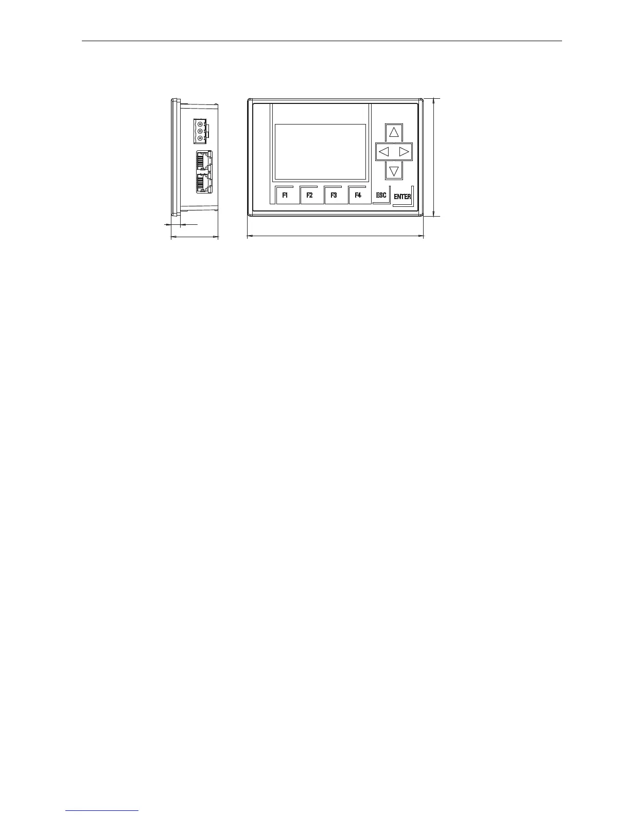
FL1F-RD1
The Text Display includes a wider display area than onboard display. It includes four
programmable cursor keys, four programmable function keys, an ESC key, and an ENTER
key. You use the Ethernet cable to connect from the Ethernet interface on the right side of the
Text Display to the Ethernet interface on the Base Module.
How to identify the IDEC SmartRelay
The IDEC SmartRelay identifier informs you of various properties.
Base module
FL1F- ①②③④⑤
① B: Base module without display
H: Base module with display
② Number of Inputs and Outputs
③ R: Relay output
S: Tr. (source) output
④ C: With clock
⑤ D: 24V DC
E: 12/24V DC
A: 24V AC/DC
C: 100...240V AC/DC
Expansion module
Digital module
FL1F-M ①②③④
① Number of Inputs and Outputs
② B1: 24V DC B2: 12/24V DC
C2: 100...240V AC/DC D2: 24V AC/DC
③ S: Tr. (source) output R: Relay output
④ Terminal type 2: non-removable terminal
①
Power supply
②
Ethernet interfaces