IDEC SmartRelay Manual
35
IDEC SmartRelay installation and wiring
2.3 iring IDEC SmartRelay
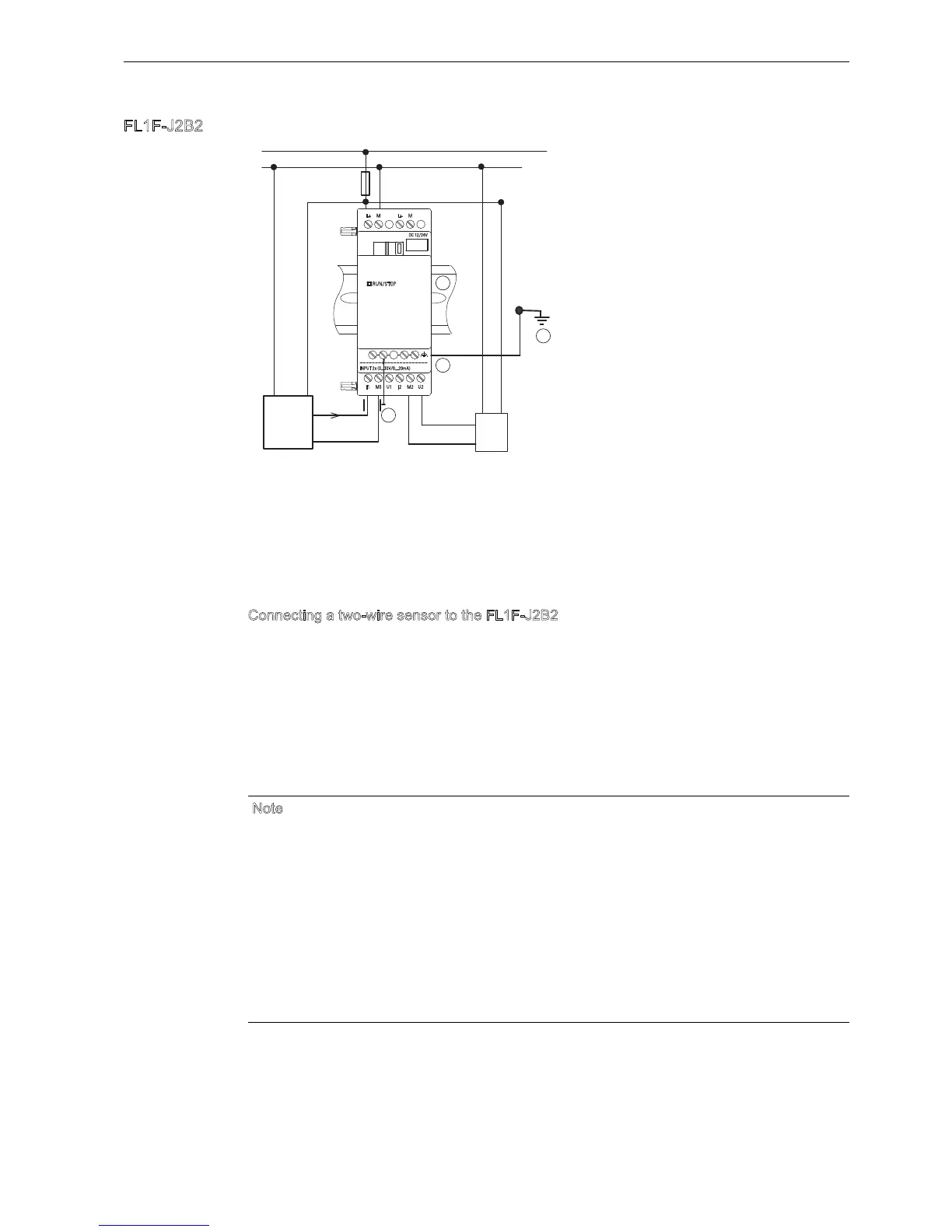
FL1F-2B2
The illustration above shows an example of four-wire current measurement and two-wire
voltage measurement.
C
onnecting a two-wire sensor to the FL1F-2B2
ire up the two-wire sensors connecting wires as follows:
1. Connect the sensors output to connection U (0V to 10 V voltage measurement) or to
connection I (0/4mA to 20mA current measurement) of the FL1F-2B2 module.
2. Connect the plus connector on the sensor to the 24 V supply voltage (L).
3. Connect the ground connection of the current output M (on the right side of the sensor, as
shown in the figure above) to the corresponding M input (M1 or M2) on the FL1F-2B2
module.
FE terminal for connecting earth and
shielding the cable
Shielded cable
Earth
Standard DIN rail
Note
Fluctuating analog values can occur if you do not mount/correctly mount the screening on the
connecting wire from the analog valuator device to the analog FL1F-2B2 expansion module
(encoder wire).
To avoid fluctuating analog values when using these expansion modules, take the following
measures:
Use only shielded cable.
Shorten the cable as much a possible. The cable must not be more than 10 meters long.
Clamp the cable on one side only and clamp it only to the FE terminal on the FL1F-2B2/
2BM2 expansion module.
Connect the earth to the FE terminal on the expansion module.
INPUT 2x (0...10V/0...20mA)
DC 12/24V
RUN/STOP
L+
I1 I2M1 M2U1 U2
L+ MM