IDEC SmartRelay installation and wiring
2.3 Wiring IDEC SmartRelay
IDEC SmartRelay Manual
36
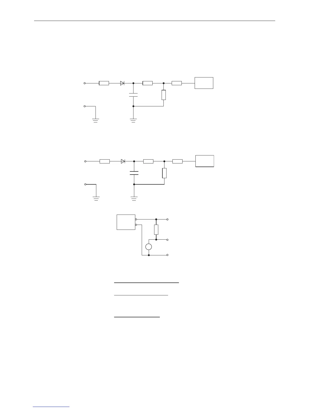
Input Internal Circuit
FL1F-H12RCC / FL1F-B12RCC
Digital AC/DC Input
FL1F-M08C2R2
Digital AC/DC Input
When using the AC two-wire sensor
390kΩ
120nF 43kΩ
180kΩ 270kΩ
I1
〜
I8
Internal
N
Circuit
Note : Bleeder resistance (R1) calcuation
The voltage drop across the load (R1) must be less than 40V while the
sensor is turned off.
R1 must satisfy the following three conditions.
Condition 1: R1 (Ω) ≤
Maximum input OFF voltage (= 40V AC)
Maximum sensor leakage current (A)
Condition 2: R1 (Ω) ≤
Sensor power voltage (V)
Minimum sensor load current (A)
Condition 3: P
R1
(W) ≥ × 3 (3: recommended allowance)
{Sensor power voltage (V)}
2
R1 resistance (Ω)