100©2018 Integrated Device Technology, Inc September 12, 2018
8A3xxxx Family Programming Guide
GPIO_USER_CONTROL.GPIO8_TO_15_OUT
Write these bits to define the level on a GPIO output pin when configured for user output control.
TRIGGER: Writing to this byte triggers a read and activation in hardware of all the bytes of the GPIO_USER_CONTROL module.
GPIO4_DRIVE_LEVEL[4] R/W 0 GPIO pin 4 drive level.
Valid only if GPIO_FUNCTION is disabled and 'gpio_control_dir' is output.
0 = drive low
1 = drive high
GPIO3_DRIVE_LEVEL[3] R/W 0 GPIO pin 3 drive level.
Valid only if GPIO_FUNCTION is disabled and 'gpio_control_dir' is output.
0 = drive low
1 = drive high
GPIO2_DRIVE_LEVEL[2] R/W 0 GPIO pin 2 drive level.
Valid only if GPIO_FUNCTION is disabled and 'gpio_control_dir' is output.
0 = drive low
1 = drive high
GPIO1_DRIVE_LEVEL[1] R/W 0 GPIO pin 1 drive level.
Valid only if GPIO_FUNCTION is disabled and 'gpio_control_dir' is output.
0 = drive low
1 = drive high
GPIO0_DRIVE_LEVEL[0] R/W 0 GPIO pin 0 drive level.
Valid only if GPIO_FUNCTION is disabled and 'gpio_control_dir' is output.
0 = drive low
1 = drive high
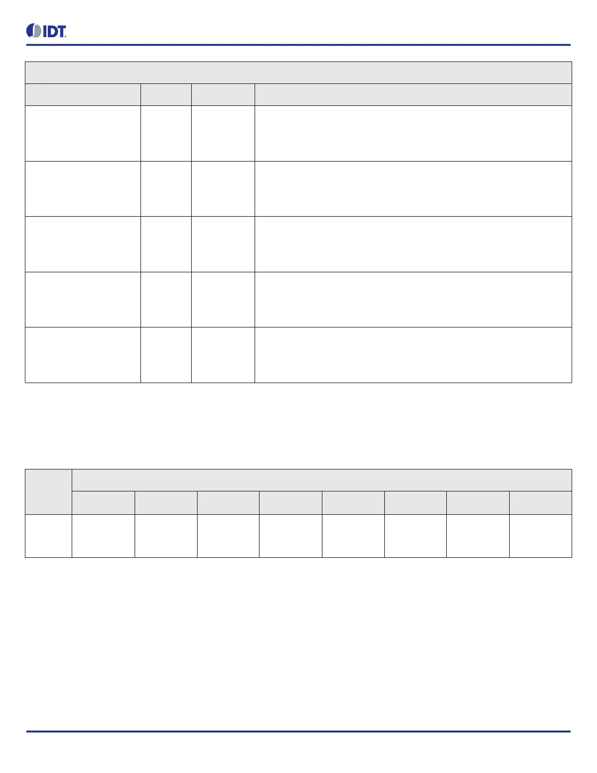
Table 121: GPIO_USER_CONTROL.GPIO8_TO_15_OUT Bit Field Locations and Descriptions
Offset
Address
(Hex)
GPIO_USER_CONTROL.GPIO8_TO_15_OUT Bit Field Locations
D7 D6 D5 D4 D3 D2 D1 D0
001h GPIO15_DRI
VE_LEVEL[7
]
GPIO14_DRI
VE_LEVEL[6
]
GPIO13_DRI
VE_LEVEL[5
]
GPIO12_DRI
VE_LEVEL[4
]
GPIO11_DRI
VE_LEVEL[3
]
GPIO10_DRI
VE_LEVEL[2
]
GPIO9_DRIV
E_LEVEL[1]
GPIO8_DRIV
E_LEVEL[0]
GPIO_USER_CONTROL.GPIO0_TO_7_OUT Bit Field Descriptions
Bit Field Name Field Type Default Value Description