145©2018 Integrated Device Technology, Inc September 12, 2018
8A3xxxx Family Programming Guide
DPLL_0.DPLL_UPDATE_RATE_CFG
DPLL loop filter update rate configuration.
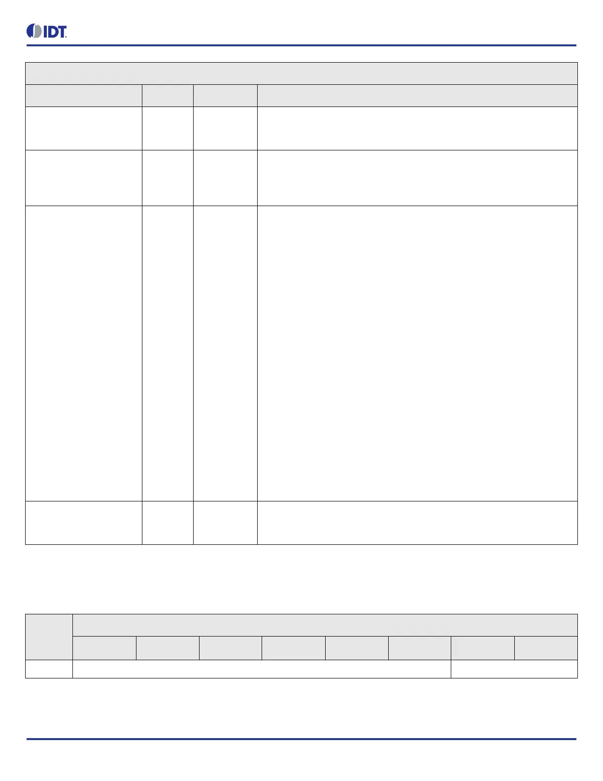
DPLL_0.DPLL_CTRL_2 Bit Field Descriptions
Bit Field Name Field Type Default Value Description
FRAME_SYNC_PULSE_R
ESYNC_EN[7]
R/W 0 Enable frame pulse or sync pulse periodic re-synchronization in locked state.
0 = disabled
1 = enabled
FRAME_SYNC_MODE[6:5
]
R/W 0 Select frame pulse mode or sync pulse mode.
0 = disabled
1 = frame pulse mode
2 = sync pulse mode
EXT_FB_REF_SELECT[4:
1]
R/W 0 Index of reference input selected as feedback for this DPLL.
External feedback must be the same frequency as ALL input references that
this DPLL locks to.
If INPUT_n.IN_MODE.MUX_GPIO_IN = 1, then the corresponding GPIO to
input pin mapping is in effect.
Ex. When INPUT_0.IN_MODE.MUX_GPIO_IN = 1, then INPUT8 is replaced
with the signal from GPIO 0.
0x0 = Input 0
0x1 = Input 1
0x2 = Input 2
0x3 = Input 3
0x4 = Input 4
0x5 = Input 5
0x6 = Input 6
0x7 = Input 7
0x8 = Input 8 (GPIO 0)
0x9 = Input 9 (GPIO 15)
0xA = Input 10 (GPIO 14)
0xB = Input 11 (GPIO 13)
0xC = Input 12 (GPIO 12)
0xD = Input 13 (GPIO 11)
0xE = Input 14 (GPIO 10)
0xF = Input 15 (GPIO 3)
EXT_FB_EN[0] R/W 0 Enable external feedback mode.
0 = disabled
1 = enabled
Table 177: DPLL_0.DPLL_UPDATE_RATE_CFG Bit Field Locations and Descriptions
Offset
Address
(Hex)
DPLL_0.DPLL_UPDATE_RATE_CFG Bit Field Locations
D7 D6 D5 D4 D3 D2 D1 D0
005h RESERVED[7:2] UPDATE_RATE_CFG[1:0]
 Loading...