236©2018 Integrated Device Technology, Inc September 12, 2018
8A3xxxx Family Programming Guide
GPIO_0.GPIO_DPLL_INDICATOR
Select the DPLL to be used to drive this GPIO. Applies when GPIO_FUNCTION is equal to 'lock indicator' or 'holdover indicator'.
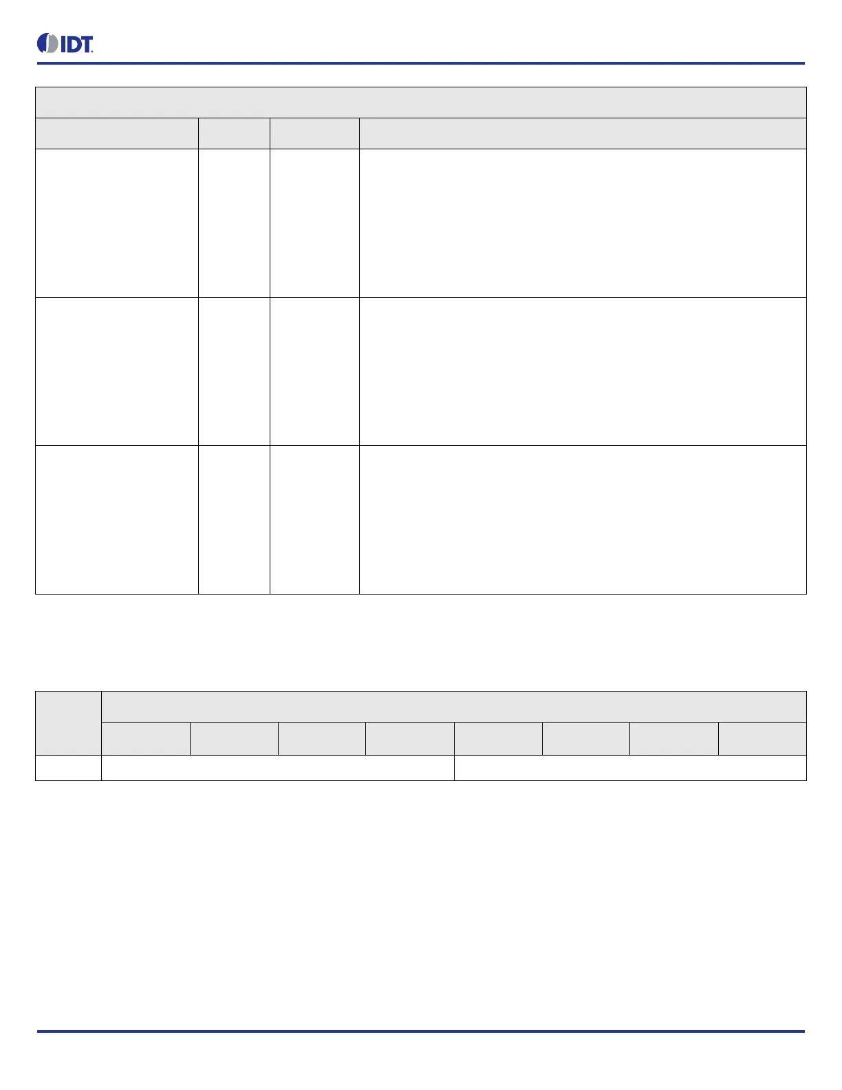
TOD_TRIG_2[2] R/W 0 Select TOD of DPLL 2 to be triggered by this GPIO.
The TOD read/write operation is triggered on the rising edge of this GPIO. The
tod_write_selection or tod_read_trigger for TOD 2 has to be equal to 'Selected
GPIO'.
CAUTION: if more than one GPIO is used to trigger the same TOD, the
behaviour is undefined.
0 = disabled
1 = enabled
TOD_TRIG_1[1] R/W 0 Select TOD of DPLL 1 to be triggered by this GPIO.
The TOD read/write operation is triggered on the rising edge of this GPIO. The
tod_write_selection or tod_read_trigger for TOD 1 has to be equal to 'Selected
GPIO'.
CAUTION: if more than one GPIO is used to trigger the same TOD, the
behaviour is undefined.
0 = disabled
1 = enabled
TOD_TRIG_0[0] R/W 0 Select TOD of DPLL 0 to be triggered by this GPIO.
The TOD read/write operation is triggered on the rising edge of this GPIO. The
tod_write_selection or tod_read_trigger for TOD 0 has to be equal to 'Selected
GPIO'.
CAUTION: if more than one GPIO is used to trigger the same TOD, the
behaviour is undefined.
0 = disabled
1 = enabled
Table 307: GPIO_0.GPIO_DPLL_INDICATOR Bit Field Locations and Descriptions
Offset
Address
(Hex)
GPIO_0.GPIO_DPLL_INDICATOR Bit Field Locations
D7 D6 D5 D4 D3 D2 D1 D0
004h RESERVED[7:4] DPLL_INDEX[3:0]
GPIO_0.GPIO_TOD_TRIG Bit Field Descriptions
Bit Field Name Field Type Default Value Description
 Loading...