237©2018 Integrated Device Technology, Inc September 12, 2018
8A3xxxx Family Programming Guide
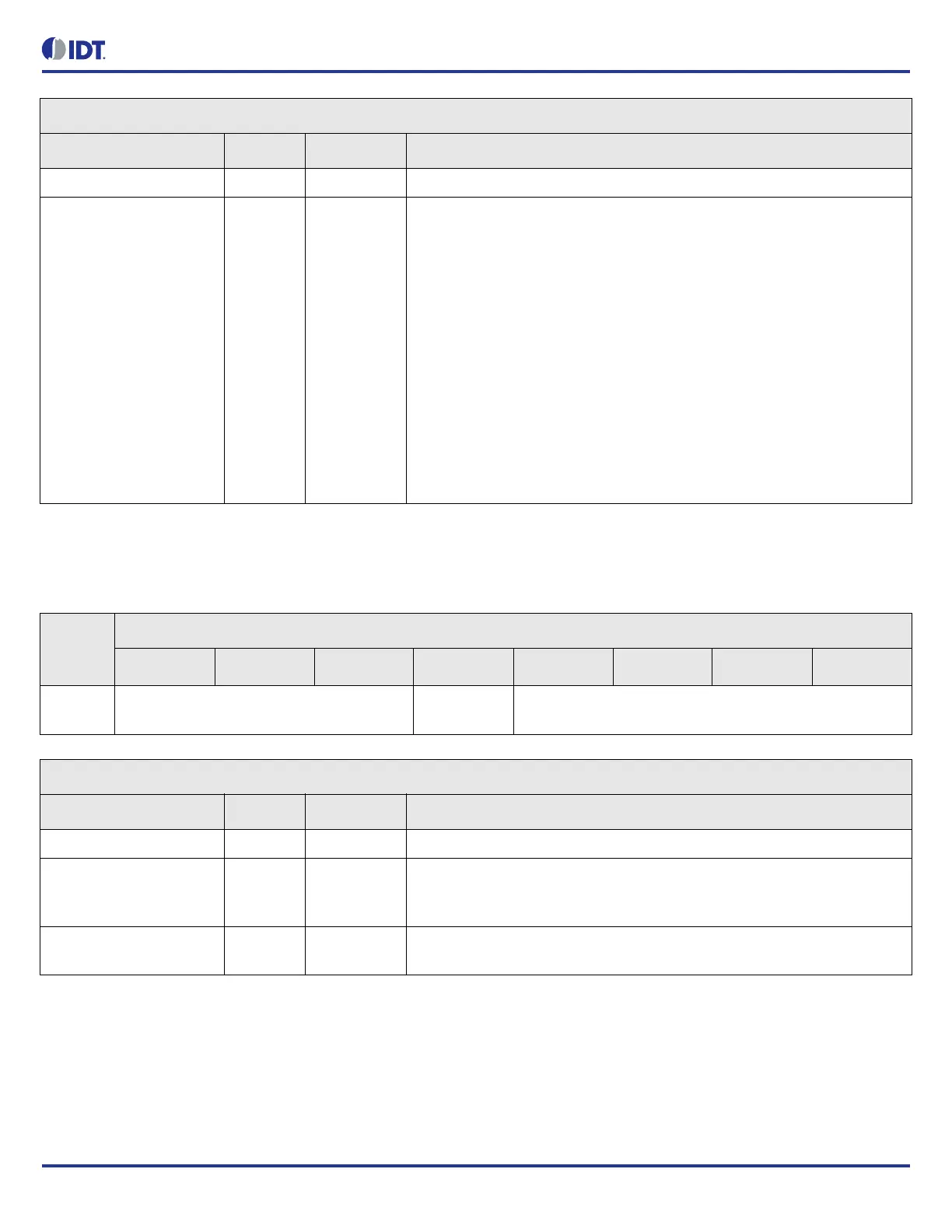
GPIO_0.GPIO_LOS_INDICATOR
Configure the GPIO LOS indicator. Applies when GPIO_FUNCTION is equal to 'LOS indicator'.
GPIO_0.GPIO_DPLL_INDICATOR Bit Field Descriptions
Bit Field Name Field Type Default Value Description
RESERVED N/A - This field must not be modified from the read value
DPLL_INDEX[3:0] R/W 0 DPLL index used by lock indicator or holdover indicator function.
The GPIO level is active when the DPLL is in locked state when
GPIO_n.GPIO_FUNCTION = lock indicator.
The GPIO level is active when the DPLL is in holdover state when
GPIO_n.GPIO_FUNCTION = holdover indicator.
0 = DPLL0
1 = DPLL1
2 = DPLL2
3 = DPLL3
4 = DPLL4
5 = DPLL5
6 = DPLL6
7 = DPLL7
8 = SYS_DPLL
Table 308: GPIO_0.GPIO_LOS_INDICATOR Bit Field Locations and Descriptions
Offset
Address
(Hex)
GPIO_0.GPIO_LOS_INDICATOR Bit Field Locations
D7 D6 D5 D4 D3 D2 D1 D0
005h RESERVED[7:5] ACTIVE_LEV
EL[4]
REFMON_INDEX[3:0]
GPIO_0.GPIO_LOS_INDICATOR Bit Field Descriptions
Bit Field Name Field Type Default Value Description
RESERVED N/A - This field must not be modified from the read value
ACTIVE_LEVEL[4] R/W 0 Level of active GPIO LOS indicator.
0 = active low
1 = active high
REFMON_INDEX[3:0] R/W 0 Reference monitor index.
Select the reference monitor which raises the LOS alarm.