85©2018 Integrated Device Technology, Inc September 12, 2018
8A3xxxx Family Programming Guide
STATUS.OUTPUT_TDC_CFG_STATUS
Indicates when the output TDC is ready for use.
STATUS.OUTPUT_TDC0_STATUS
Indicates the hardware output TDC instance assigned and the status code.
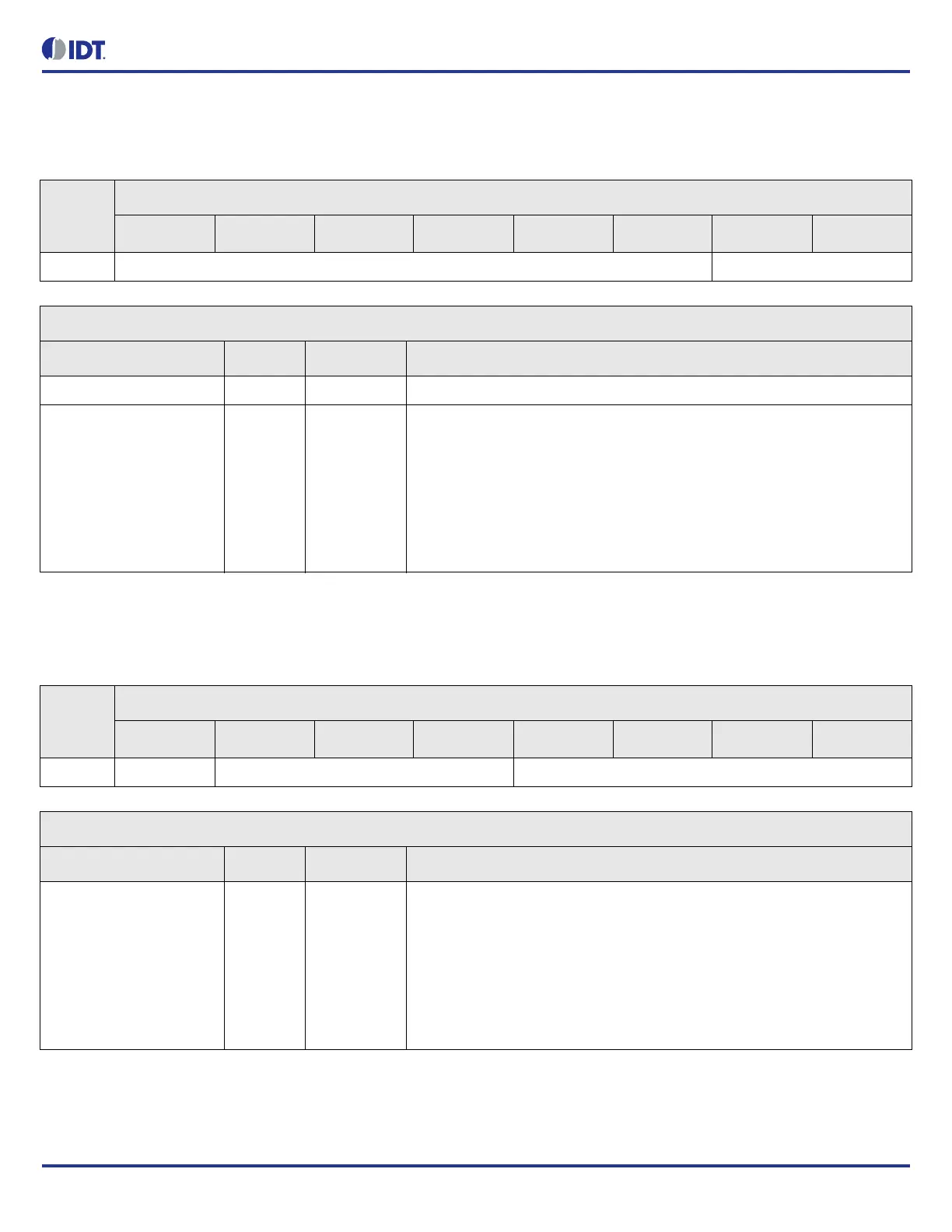
Table 94: STATUS.OUTPUT_TDC_CFG_STATUS Bit Field Locations and Descriptions
Offset
Address
(Hex)
STATUS.OUTPUT_TDC_CFG_STATUS Bit Field Locations
D7 D6 D5 D4 D3 D2 D1 D0
0ACh RESERVED[7:2] STATE[1:0]
STATUS.OUTPUT_TDC_CFG_STATUS Bit Field Descriptions
Bit Field Name Field Type Default Value Description
RESERVED N/A - This field must not be modified from the read value
STATE[1:0] R/O 0 Indicates whether the output TDC is ready to be used.
Output TDC is by default disabled.
Need to enable with OUTPUT_TDC_CFG_GBL_2.enable. After enabling, it
takes time for the output TDC clock to stabilize.
Output TDC is ready for use when in Ready state.
0 = disabled
1 = initializing
2 = ready
Table 95: STATUS.OUTPUT_TDC0_STATUS Bit Field Locations and Descriptions
Offset
Address
(Hex)
STATUS.OUTPUT_TDC0_STATUS Bit Field Locations
D7 D6 D5 D4 D3 D2 D1 D0
0ADh VALID[7] RESERVED[6:4] STATUS[3:0]
STATUS.OUTPUT_TDC0_STATUS Bit Field Descriptions
Bit Field Name Field Type Default Value Description
VALID[7] R/O 0 Indicates a valid measurement or alignment has met target phase offset.
When go bit is set, valid is cleared.
Measurement mode: Indicates when OUTPUT_TDCn_MEASUREMENT is
valid.
Alignment mode: Indicates when all the alignment targets are within the
OUTPUT_TDC_CTRL_1.TARGET_PHASE_OFFSET.
0 = invalid
1 = valid