110©2018 Integrated Device Technology, Inc September 12, 2018
8A3xxxx Family Programming Guide
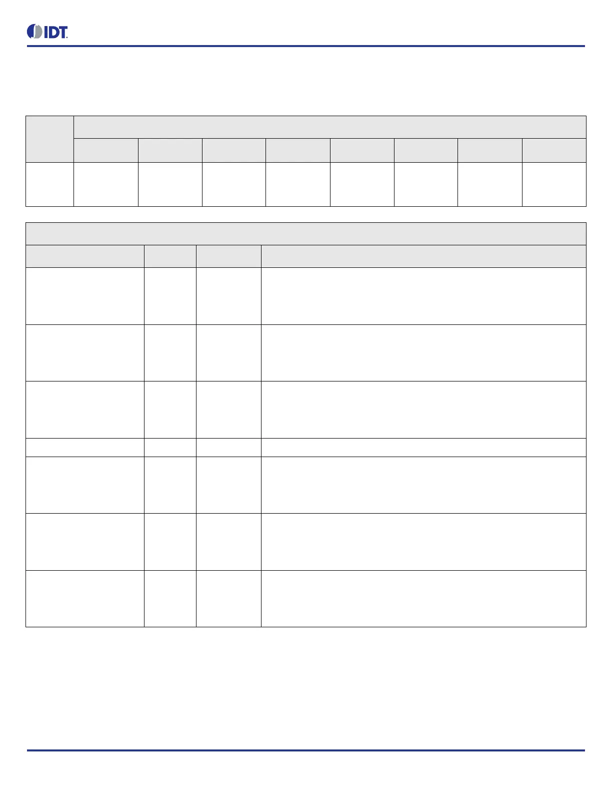
ALERT_CFG.IN5_4_MON_ALERT_MASK
GPIO alert enable masks (frequency offset, no activity, loss of signal) for reference monitors 4 and 5.
Table 135: ALERT_CFG.IN5_4_MON_ALERT_MASK Bit Field Locations and Descriptions
Offset
Address
(Hex)
ALERT_CFG.IN5_4_MON_ALERT_MASK Bit Field Locations
D7 D6 D5 D4 D3 D2 D1 D0
002h RESERVED[
7]
IN5_FREQ_
OFFS_LIM_
MASK[6]
IN5_NO_AC
TIVITY_MAS
K[5]
IN5_LOS_M
ASK[4]
RESERVED[
3]
IN4_FREQ_
OFFS_LIM_
MASK[2]
IN4_NO_AC
TIVITY_MAS
K[1]
IN4_LOS_M
ASK[0]
ALERT_CFG.IN5_4_MON_ALERT_MASK Bit Field Descriptions
Bit Field Name Field Type Default Value Description
IN5_FREQ_OFFS_LIM_M
ASK[6]
R/W 0 Input 5 frequency offset limit enable mask.
If enabled, GPIO alert becomes active when in5_freq_offs_lim_sticky bit is set.
0 = disabled
1 = enabled
IN5_NO_ACTIVITY_MASK
[5]
R/W 0 Input 5 no activity enable mask.
If enabled, GPIO alert becomes active when in5_no_activity_sticky bit is set.
0 = disabled
1 = enabled
IN5_LOS_MASK[4] R/W 0 Input 5 LOS enable mask.
If enabled, GPIO alert becomes active when in5_los_sticky bit is set.
0 = disabled
1 = enabled
RESERVED N/A - This field must not be modified from the read value
IN4_FREQ_OFFS_LIM_M
ASK[2]
R/W 0 Input 4 frequency offset limit enable mask.
If enabled, GPIO alert becomes active when in4_freq_offs_lim_sticky bit is set.
0 = disabled
1 = enabled
IN4_NO_ACTIVITY_MASK
[1]
R/W 0 Input 4 no activity enable mask.
If enabled, GPIO alert becomes active when in4_no_activity_sticky bit is set.
0 = disabled
1 = enabled
IN4_LOS_MASK[0] R/W 0 Input 4 LOS enable mask.
If enabled, GPIO alert becomes active when in4_los_sticky bit is set.
0 = disabled
1 = enabled