99©2018 Integrated Device Technology, Inc September 12, 2018
8A3xxxx Family Programming Guide
Module: GPIO_USER_CONTROL
Configures the controls of the GPIO .
GPIO_USER_CONTROL.GPIO0_TO_7_OUT
Write these bits to define the level on a GPIO output pin when configured for user output control.
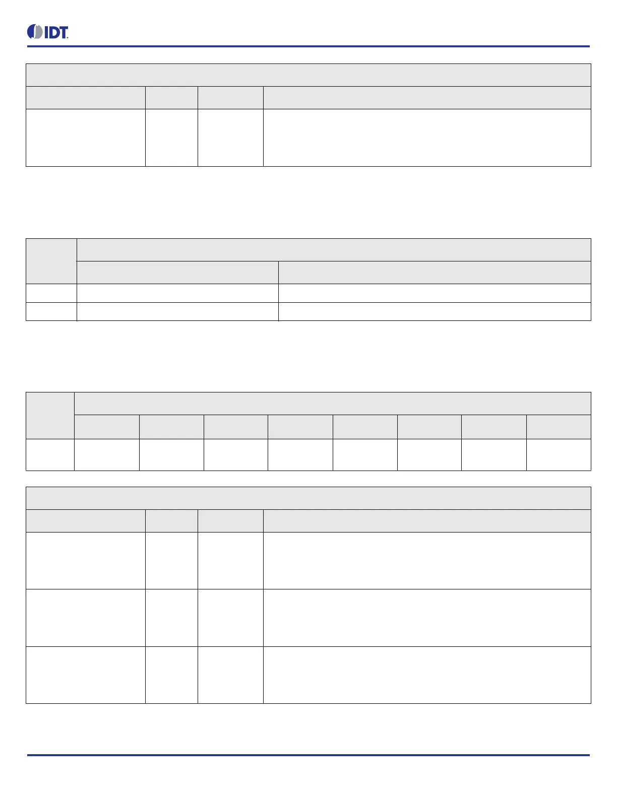
STATUS.DPLL7_PHASE_PULL_IN_STATUS Bit Field Descriptions
Bit Field Name Field Type Default Value Description
REMAINING_TIME[7:0] R/O 0 Unsigned 8-bit phase pull-in time to finish in seconds.
If the value of this field < 255, the actual remaining time is between
(remaining_time) and (remaining_time + 1) seconds. If the value = 255, it
implies the actual remaining time >= 255 seconds.
Table 119: GPIO_USER_CONTROL Register Index
Offset
(Hex)
Register Module Base Address: C160h
Individual Register Name Register Description
000h GPIO_USER_CONTROL.GPIO0_TO_7_OUT GPIO output control.
001h GPIO_USER_CONTROL.GPIO8_TO_15_OUT GPIO output control.
Table 120: GPIO_USER_CONTROL.GPIO0_TO_7_OUT Bit Field Locations and Descriptions
Offset
Address
(Hex)
GPIO_USER_CONTROL.GPIO0_TO_7_OUT Bit Field Locations
D7 D6 D5 D4 D3 D2 D1 D0
000h GPIO7_DRIV
E_LEVEL[7]
GPIO6_DRIV
E_LEVEL[6]
GPIO5_DRIV
E_LEVEL[5]
GPIO4_DRIV
E_LEVEL[4]
GPIO3_DRIV
E_LEVEL[3]
GPIO2_DRIV
E_LEVEL[2]
GPIO1_DRIV
E_LEVEL[1]
GPIO0_DRIV
E_LEVEL[0]
GPIO_USER_CONTROL.GPIO0_TO_7_OUT Bit Field Descriptions
Bit Field Name Field Type Default Value Description
GPIO7_DRIVE_LEVEL[7] R/W 0 GPIO pin 7 drive level.
Valid only if GPIO_FUNCTION is disabled and 'gpio_control_dir' is output.
0 = drive low
1 = drive high
GPIO6_DRIVE_LEVEL[6] R/W 0 GPIO pin 6 drive level.
Valid only if GPIO_FUNCTION is disabled and 'gpio_control_dir' is output.
0 = drive low
1 = drive high
GPIO5_DRIVE_LEVEL[5] R/W 0 GPIO pin 5 drive level.
Valid only if GPIO_FUNCTION is disabled and 'gpio_control_dir' is output.
0 = drive low
1 = drive high