91©2018 Integrated Device Technology, Inc September 12, 2018
8A3xxxx Family Programming Guide
STATUS.OUTPUT_TDC3_MEASUREMENT
Indicates output TDC 3 measurement.
STATUS.OUTPUT_TDC2_MEASUREMENT Bit Field Descriptions
Bit Field Name Field Type Default Value Description
PHASE[47:0] R/O 0 Output TDC measurement.
Signed 48-bit integer in picoseconds.
Measurement = sum of samples / number of samples
A sample is collected every 100us.
Positive value indicates the target edge leads the source edge.
i.e.. source edge is to the left of the target edge
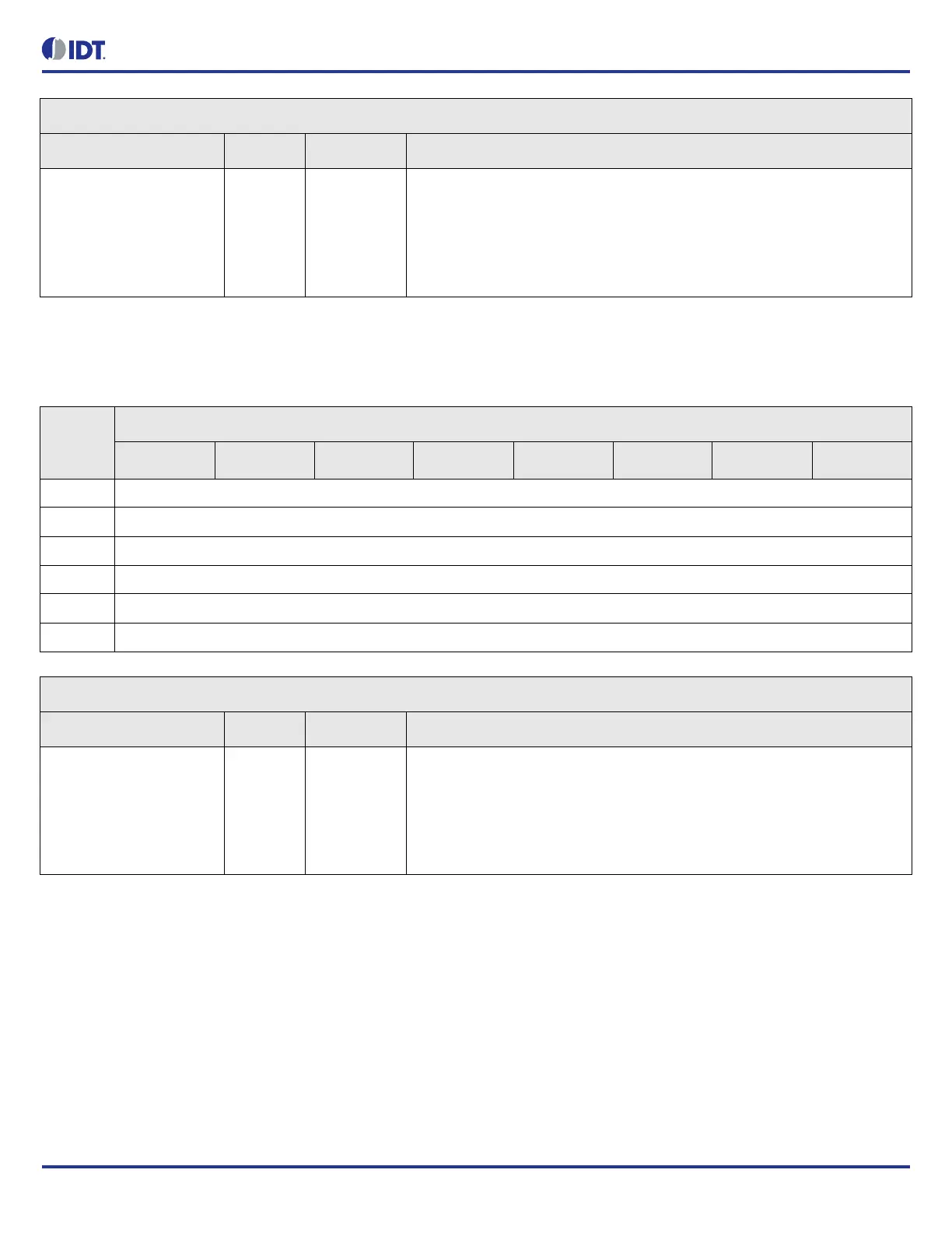
Table 102: STATUS.OUTPUT_TDC3_MEASUREMENT Bit Field Locations and Descriptions
Offset
Address
(Hex)
STATUS.OUTPUT_TDC3_MEASUREMENT Bit Field Locations
D7 D6 D5 D4 D3 D2 D1 D0
0D4h PHASE[7:0]
0D5h PHASE[15:8]
0D6h PHASE[23:16]
0D7h PHASE[31:24]
0D8h PHASE[39:32]
0D9h PHASE[47:40]
STATUS.OUTPUT_TDC3_MEASUREMENT Bit Field Descriptions
Bit Field Name Field Type Default Value Description
PHASE[47:0] R/O 0 Output TDC measurement.
Signed 48-bit integer in picoseconds.
Measurement = sum of samples / number of samples
A sample is collected every 100us.
Positive value indicates the target edge leads the source edge.
i.e.. source edge is to the left of the target edge