3-18 Basic DMM Operation Model 2700 Multimeter/Switch System User’s Manual
Model 7700 switching module
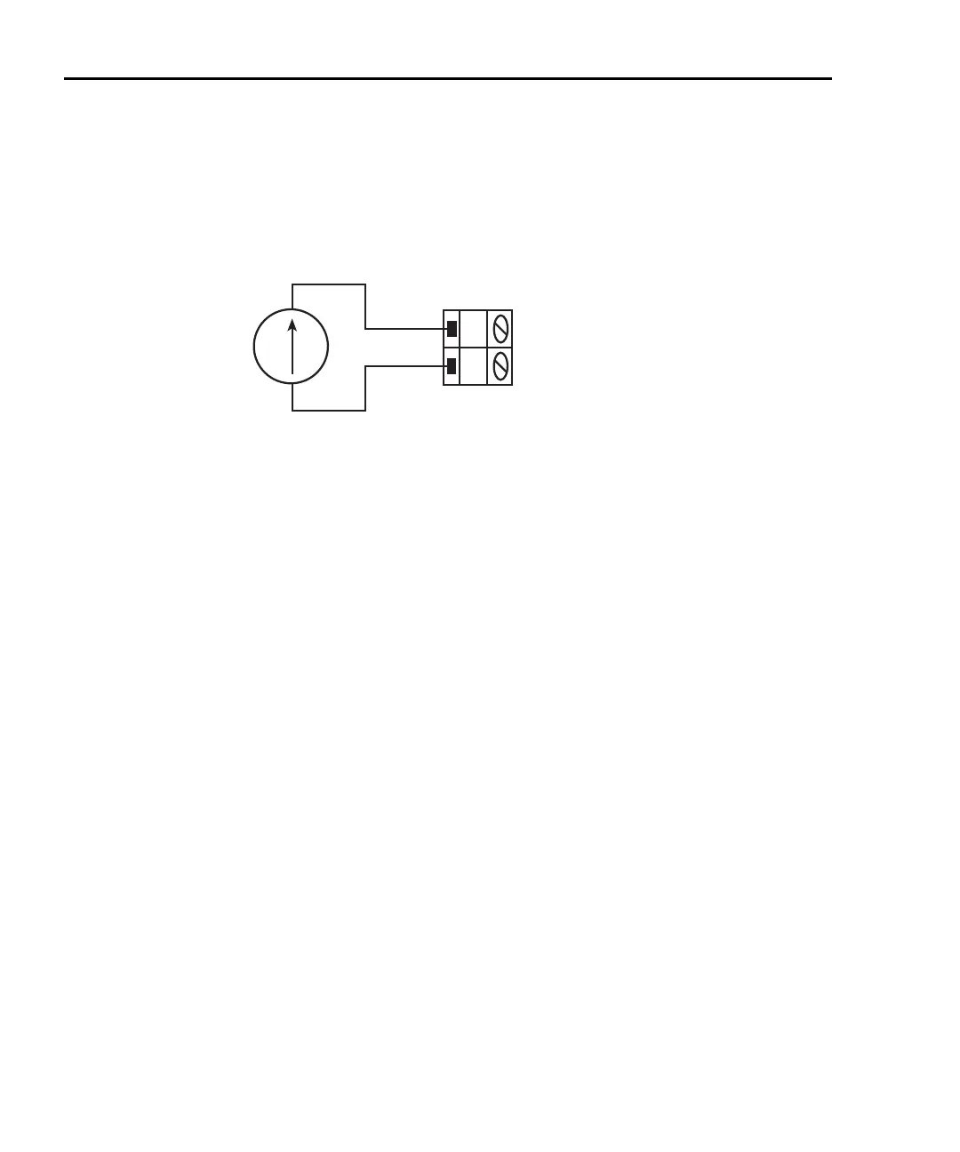
Connections for the Model 7700 switching module are shown in Figure 3-7. Note that
only channels 21 and 22 can be used for current measurements.
Figure 3-7
DCI and ACI connections using Model 7700 switching module
Amps measurement procedure
NOTE Make sure the INPUTS switch is in the correct position. To use front panel
inputs, it has to be in the “F” (out) position. For switching modules, it has to be
in the “R” (in) position.
1. If a switching channel is presently closed (displayed), press OPEN to open it.
2. Select the amps measurement function by pressing DCI or ACI.
3. Use the RANGE Δ and ∇ keys to select a measurement range consistent with the
expected current, or press AUTO to select autoranging (AUTO annunciator turns
on). Details on range are provided in
Section 4.
4. Apply the current(s) to be measured.
CAUTION Do not apply more than 3A to the input or the AMPS fuse will blow.
Model 7700 switching module — When performing current
measurements, the maximum allowable voltage is 60VDC or 30V
RMS. Exceeding these limits could cause damage to the switching
module.
5. If using a switching module, use the and keys to close the desired amps
channel (for the Model 7700, 21 or 22). All other channels will be open.
Model 7700
Switching
Module
H
L
CH 21 or 22
Caution: Maximum input: 60VDC or 30V RMS, 3A switched,
60W, 125VA maximum
Current
Source

 Loading...


